quinta-feira, 3 de março de 2016
KS Gorshkov, V. Tokarev, VV Filaretov SYNTHESIS AND ANALYSIS ELECTRICAL CIRCUITS-Анализ и синтез электрических цепей -К. С. Горшков, Ю. В. Токарев, В. В. Филаретов
LINK ORIGINAL
http://venec.ulstu.ru/lib/disk/2014/68.pdf
LINK ALTERNATIVO
http://www.mediafire.com/download/cpbhezk1t7kkcls/SYNTHESIS_AND_ANALYSIS_ELECTRICAL_CIRCUITS-KS_Gorshkov%2C_V._Tokarev%2C_VV_Filaretov.pdf
quarta-feira, 2 de março de 2016
Matrix method of analysis of electric circuits Melnikov-Матричный метод анализа электрических цепей Мельников Н.А.
Matrix method of analysis of electric circuits Melnikov NA
The book presents the fundamentals of the generalized method of analysis Set the mode of complex equivalent circuits of electric circuits on the basis of application of the device matrix and the elements of a topological graph theory.
LINK ORIGINAL FORMATO DJVU
http://mexalib.com/download/22978
LINK ALTERNATIVO FORMATO PDF
http://www.mediafire.com/download/pr7w4ualg6v60pa/Matrix_method_of_analysis_of_electric_circuits-Melnikov.pdf
quinta-feira, 18 de fevereiro de 2016
A Design and Fabrication of PWM Power Amplifier for Digital Audio signal Jun-Sung, Lee Dept. of Electronical and Computer Engineering The Graduate School SungKyunKwan University
A Design and Fabrication of PWM Power
Amplifier for Digital Audio signal
Jun-Sung, Lee
Dept. of Electronical and Computer Engineering
The Graduate School
SungKyunKwan University
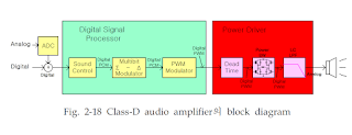
Amplifiers in electronics are used in a wide variety of applications in audio, video and telecommunications. Conventional amplifiers such as Class-A, Class-B, Class-AB based on linear circuit technology have good distortion characteristics, but yield poor efficiency and need large size of cooling material. On the other hand, the Class-D amplifier has good efficiency and small size, but relatively bad Total Harmonic Distortion(THD) and Signal to Noise Ratio(SNR) because of a switching mode operation. Recent researches have demonstrated the feasibility of realizing an almost complete digital audio system. The characteristics of THD and SNR of the Class-D amplifier depend on the duty ratio, rising falling and settling time of output PWM(Pulse Width Modulation) signals. This paper presents a one-chip monolithic integrated circuit(IC) of the two-channel Class-D audio power amplifier with high efficiency and lower THD using a 0.65[㎛], 40[V] bCDMOS process. Each channel can drive 50[W] power and a single channel power of 100[W] can be obtained through the external control signal. The Class-D amplifier at the output stage is controlled by generating a PWM signal. The conversion of the digital audio data to PWM pulse stream is performed by using PCM to PWM converter and results in the elimination of the THD. The results of the study are as follows: 1. The design and implementation of a 2-channel Class-D amplifier using 40[V] bCDMOS technology and the evaluation on the performance of designed class-D amplifier through fabricated wafer. ① The size of die is 3,700[㎛]×5,100[㎛]. The output power transistor occupies 60[%] of the die area. The output current driving capability and on-resistance are mainly considered features. ② The THD is 0.07[%] at 1[W] output power. ③ The Efficiency is 92[%] at 20[W] output power. The efficiency is getting worse when the output power is below 5[W] and above 35[W]. At a lower power consumption mode, the internal power takes up a larger portion of the total power. On the other hand, at a high power mode, power consumed by the resistance of bonding wire, routing metal and on-resistance of the MOS transistor are more dominant. These results are obtained by measuring selected samples out of packaged products. But, Some parts of the circuit need improvement before the mass production.
LINK
http://www.mediafire.com/view/ci41jtvncuyxdd0/PWM_POWER_AMPLIFIER.pdf
quarta-feira, 17 de fevereiro de 2016
TEORIA DE CIRCUITOS ELÉCTRICOS LINEALES CON EJERCICIOS Y TAREAS Autor: MR Shebes -Теория линейных электрических цепей в упражнениях и задачах Автор: Шебес М. Р.-1967
Descripción:
El libro proporciona un material y fórmulas teórica breve, problemas típicos con soluciones y explicaciones detalladas, para la solución de tareas independientes. Un gran número de ejemplos muestra el uso de los métodos básicos de cálculo, tal como un circuito eléctrico en las condiciones estables y transitorias. Con un número significativo de problemas resueltos con diagramas vectoriales. Las técnicas que se muestran de su construcción. El manual está dirigido a los estudiantes de las escuelas eléctrica y facultades de Ingeniería.
LINK
http://www.mediafire.com/view/krl6nzz34r0p4ie/TEORIA_DE_CIRCUITOS_LINEALES-SHEBA-1967.pdf
Design and Implementation of an SMPS for UPS Charging and Discharging System using the DC-DC buck converter method by Kim dong-Rok Department of Electronics & Mechatronics Engineering Graduate School of Industrial Technology and Management Korea Polytechnic University
Design and Implementation of an SMPS for UPS
Charging and Discharging System using the DC-DC
buck converter method
by Kim dong-rok
Advisor : Prof. Lee Sang-ho, Ph.D.
Department of Electronics & Mechatronics Engineering
Graduate School of Industrial Technology and Management
Korea Polytechnic University
The purpose of this paper is to develop the SMPS(Switched Mode Power Supply) for the implementation of the charge-discharge system of the UPS(Uninterruptible Power System) with the DC-DC buck converter. The proposed SMPS is designed to be able to switch two different output voltage levels and it has provided a circuit configuration for the two output voltage. This SMPS operated the generator circuit of the output voltage in response to the state of the High/Low of the output selected signal. As the rest of the circuit groups are not driven, unnecessary power consumption is minimized. The equipment with a high battery power is possible to charge by using the 2 fuse-2 outlet cable on the 12~70V DC area. The equipment with a low battery power is possible to charge by using the 8Fuse-8prong cable on the 12V DC area. Eventually, the developed SMPS system is capable of controlling by a simple switch as well as efficient.
LINK http://www.mediafire.com/view/hyxxmty5avzwr32/Design_and_Implementation_of_an_SMPS_for_UPS.pdf
sábado, 6 de fevereiro de 2016
Assinar:
Postagens (Atom)








 JOSIL ARTISTA PLASTICO FORTALEZA CEARA BRASIL AV.HERACLITO GRAÇA 41 TEL(85)32542378