AUTOR DO BLOG ENG.ARMANDO CAVERO MIRANDA SÃO PAULO BRASIL

"OBRIGADO DEUS PELA VIDA,PELA MINHA FAMILIA,PELO TRABALHO,PELO PÃO DE CADA DIA,PROTEGENOS DO MAL"

"OBRIGADO DEUS PELA VIDA,PELA MINHA FAMILIA,PELO TRABALHO,PELO PÃO DE CADA DIA,PROTEGENOS  DO MAL"

“SE SEUS PROJETOS FOREM PARA UM ANO,SEMEIE O GRÂO.SE FOREM PARA DEZ ANOS,PLANTE UMA ÁRVORE.SE FOREM PARA CEM ANOS,EDUQUE O POVO.”

“Sixty years ago I knew everything; now I know nothing; education is a progressive discovery of our own ignorance. Will Durant”

segunda-feira, 6 de fevereiro de 2017

Zero dead-time PWM method for reducing THD in offshore wind power 3-level inverter - KAN YONG -PROGRAM ENERGY SYSTEM ENGINEERING - SUNGKYUNKWAN UNIVERSITY


AAAA


ABSTRACT
 To prevent the short circuit dead time is required because it can happen the short circuit due to a difference between rising time and falling time ocurred in power semiconductor swith. However dead time cause the distortion and THD increase of output current,it is major cause of malfunction by distorted output current and high THD.
 In this paper,circuit of 3-level NPC inverter and characteristic of operation is analyzed.Also switching methods wich make the switching pattern of Zero Dead-time PWM for decreasing THD and optimization method is proposed. Proposed Zero Dead -time PWM method is explained on the basis of theoretic analysis,hardware is set for applying the proposed method.
LINK
http://www.mediafire.com/file/5k85lybur3tzl9o/PWM_DEAD_TIME_2017.pdf

sábado, 4 de fevereiro de 2017

Engenharia Elétrica e a Pós-graduação na Universidade Federal do Ceará - PROFESSOR PAULO PRAÇA ( CHEFE DO DEPARTAMENTO DE ENGENHARIA ELÉTRICA DA UNIVERSIDADE FEDERAL DE CEARÁ)-BRASIL


Neste vídeo, o Professor Paulo Praça expõe o que é a pós-graduação em Engenharia Elétrica, em particular, o programa da Universidade Federal do Ceará.
 PESSOALMENTE EU TRABALHEI DE 2006 A 2012 NA EMPRESA MICROSOL HOJE APC-SCHNEIDER,A EMPRESA MICROSOL TINHA UMA ESTREITA PARCERIA COM O PROGRAMA DE ENGENHARIA ELÉTRICA DA UNIVERSIDADE FEDERAL DE CEARÁ,ESPECIALMENTE COM O PROGRAMA DE MESTRADO E DOUTORADO,O NÍVEL ACADÊMICO DOS ALUNOS,PROFESSORES E LABORATÓRIOS SÃO EXCELENTES,EXISTE AMBIENTE PARA A PESQUISA E DESENVOLVIMENTO.

quinta-feira, 2 de fevereiro de 2017

Design and Testing of Voltage Source Inverter and Motor Control System for Electric Vehicle - Lars Helge Oplopisal - Norwegian University of Science and Technology - Department of Electric Power Engineering


Design and Testing of Voltage Source
Inverter and Motor Control System for
Electric Vehicle
Lars Helge Opsahl
Master of Energy and Environmental Engineering
Supervisor: Lars Einar Norum, ELKRAFT
JULY 2015
Submission date: July 2015
Norwegian University of Science and Technology
Department of Electric Power Engineering

Abstract

With fast rotating permanent-magnet motors and compact battery storage units, the high performance motorsport community has, in recent years, started to utilize the quick response and high torque of electrical drivetrain solutions. By recovering energy, braking into a corner, for then to utilize the same energy, boosting out again, the electrical machine gives increased performance even for the fastest racing cars. The purpose of the work presented in this Master’s thesis is to develop and produce the power electronics and motor control system needed to control such an electric machine, where the final product is used to drive a fully electric prototype racing car. The thesis presents the conceptual work, design choices, prototyping, testing and development of a 2-level voltage source inverter and motor control system. The voltage source is a battery accumulator energy storage unit, while the machine is a three-phase permanent-magnet motor. The voltage source inverter is based on insulated-gate bipolar transistors (IGBTs), controlled by a motor control system called field oriented control. On command from the driver’s throttle, the motor control system generates the required stator currents, giving the wanted output torque, supplied from the voltage source of the battery accumulator. The inverter is the connecting interface between the power source, and the rotating machinery. With the amount of energy and power needed to drive a racing car, safe and reliable operation is important. To ensure the safety of the driver and operating personnel, the system and its safety features have been through extensive testing in a laboratory setup and on the race tracks. In the system development process, simulation and modelling tools have been applied to investigate different solutions and technologies. These tools have also been used to design the electric circuits, program code and mechanical design needed for the system. The final product is installed in a racing car and shows great performance.
LINK ORIGINAL COMPLETE THESIS
https://brage.bibsys.no/xmlui/handle/11250/2368215
DIRECT LINK
https://brage.bibsys.no/xmlui/bitstream/handle/11250/2368215/13287_FULLTEXT.pdf?sequence=1&isAllowed=y

Design of a 48 V three-phase inverter For automotive applications -FREDRIK FÜRST - Department of Energy and Environment CHALMERS UNIVERSITY OF TECHNOLOGY Gothenburg, Sweden 2015


Design of a 48 V three-phase inverter: For automotive applications
Master's thesis in Electric Power Engineering

Fredrik Furst
Department of Energy and Environment
Chalmers University of Technology
Abstract
This project presents a design and construction of a three-phase inverter,
drive circuit and dc-link capacitor bank. The inverter should be able to
supply an electrical machine with 48 V and 250 A. Initial calculations and
simulations were made to get some base for the ordering of hardware. The
inverter board consists of six MOSFETs in parallel for each phase and the
PCB itself is made of aluminum to enable a thermal substrate technique.
The inverter PCBs are mounted on an aluminum frame where liquid runs
between them to cool the inverter. The drive circuit is controlled with a
dSPACE system and the tests are made with a load consisting of cables
and iron powder cores. Temperatures are measured with PT100 sensors
for the water and an infrared camera for the surfaces.
Two di erent MOSFETs were investigated, one with higher switching
losses and one with higher conduction losses. The two inverters were tested
on an RL load and the cooling system picked up around 270 W at a phase
current of 150 Arms. Theoretical calculations, performed with measured
parameters, represents the temperature measurements well. The thermal
resistance between the case and the sink in the inverter, R cs, is measured
to around 0:15 [K=W].
Index Terms: Capacitor bank, cooling system, drive circuit, dSPACE,
inverter, MOSFET, thermal evaluation.

LINK ORIGINAL COMPLETE THESIS
http://publications.lib.chalmers.se/records/fulltext/224623/224623.pdf

terça-feira, 31 de janeiro de 2017

Design of a IGBT Inverter for Large Capacity BLDC Servo Motor Driving by Hwang Minkyu Dept. of Electrical, Electronics and Control Eng. Graduate School of Engineering, Changwon National University


Design of a IGBT Inverter for Large Capacity BLDC Servo Motor Driving by Hwang Minkyu
Dept. of Electrical, Electronics and Control Eng. Graduate School of Engineering, Changwon national University (Advisor : Prof. Choi Jung Keyng, Ph.D)
ABSTRACT
 Inverter is the core module of the power electronics for converting a fixed DC voltage as a power conversion module with the AC voltage, It has been applied to a power control and motor control. In this study, we aimed to develop an inverter that is used especially for control of a kind of BLDC motor AC servo motor. The control of the inverter is composed of a circuit for generating a variable frequency, the motor phase voltages of variable amplitude, phase current using a DC voltage Vdc_link. Power switching device that is used for the built-in three-phase bridge circuit in the inverter unit is a high voltage, And For the purpose of the medium-current conduction IGBT devices it is mainly used. IGBT switching element is a tendency to use mainly the driving circuit module, because of the complexity of the gate drive circuit. In this study, we propose a method for designing an inverter of 40kW class using semikron 7 pack IGBT modules, three lower IGBT gate driving module and three upper IGBT gate driving module.

LINK
http://www.mediafire.com/file/2g1sc0hhnv3v0g5/Design_of_a_IGBT_Inverter_for_Large_Capacity_BLDC.pdf

quarta-feira, 25 de janeiro de 2017

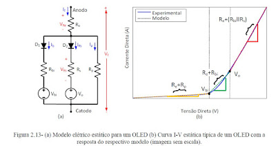
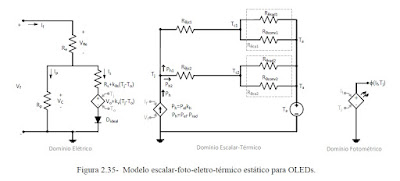
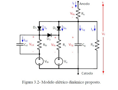
MODELAGEM E ACIONAMENTO DE DIODOS ORGÂNICOS EMISSORES DE LUZ (OLEDS) PARA SISTEMAS DE ILUMINAÇÃO - TESE DOUTORADO - Vitor Cristiano Bender -Universidade Federal de Santa Maria - BRASIL


MODELAGEM E ACIONAMENTO DE DIODOS ORGÂNICOS EMISSORES DE LUZ (OLEDS) PARA SISTEMAS DE ILUMINAÇÃO 
 Autor principal: Vitor Cristiano Bender
Outros Autores: Rafael Adaime Pinto, José Marcos Alonso Álvarez, Henrique Antônio Carvalho Braga, Marco Antônio Dalla Costa, Ricardo Nederson do Prado, Tiago Bandeira Marchesan
Grau: Tese
Idioma: PORTUGUÊS.
Publicado em: Universidade Federal de Santa Maria 2015
 Resumo: A presente tese de doutorado apresenta o estudo e a caracterização de diodos orgânicos emissores de luz (OLEDs) com a proposta de um modelo equivalente que é útil no desenvolvimento de circuitos de acionamento e na análise de OLEDs, quando aplicados em sistemas de iluminação. Inicialmente, é apresentada uma revisão bibliográfica contemplando o princípio de funcionamento e os aspectos construtivos dos OLEDs. A partir disto, um modelo que integra os aspectos de escala, fotométricos, elétricos e térmicos é proposto. Esse modelo é denominado EFET e é dividido em estático e dinâmico. Uma proposta de procedimento para identificação dos parâmetros do modelo é apresentada, juntamente com a análise do efeito da capacitância intrínseca dos OLEDs no seu desempenho elétrico, térmico e fotométrico. Com o modelo proposto pode-se predizer e simular o comportamento dos OLEDs antes de construir o sistema de iluminação, reduzindo custos e tempo de desenvolvimento. O modelo é validado empregando diferentes amostras de OLEDs. Conclusões são obtidas a partir da validação experimental e de simulações empregando simuladores elétricos e da fluidodinâmica computacional através do método de elementos finitos. Uma abordagem considerando os métodos de ajuste da intensidade luminosa de OLEDs é apresentada, evidenciando o impacto cromático provocado por cada método. Por fim, um circuito de acionamento para OLEDs baseado no conceito de capacitores chaveados é proposto. Os resultados obtidos são satisfatórios e proporcionam um incremento ao estado da arte da modelagem e acionamento de OLEDs.
LINK ORIGINAL EN LA WEB
http://bdtd.ibict.br/vufind/Record/UFSM_d3fea1ec20b7614c5d70ce14b2af02bf/Description#tabnav

LINK DIRECTO
http://cascavel.ufsm.br/tede//tde_busca/arquivo.php?codArquivo=7622

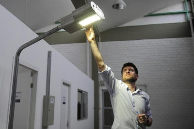
Tecnologia desenvolvida na UNIVERSIDADE FEDERAL DE SANTA MARIA (UFSM-BRASIL) pode aumentar eficiência da iluminação pública em até 40%


Instituto Nacional de Propriedade Industrial (Inpi) concedeu prêmio Patente Verde para o protótipo de luminária com a invenção O programa de pós-graduação em Engenharia Elétrica da Universidade Federal de Santa Maria (UFSM) desenvolveu uma tecnologia que pode aumentar a eficiência da iluminação pública da cidade em até 40%.

E, após cinco anos de pesquisas, o protótipo recebeu a Patente Verde, distinção do Instituto Nacional de Propriedade Industrial (Inpi) que premia projetos com características sustentáveis. É a primeira dessas distinções recebidas pela UFSM.

O engenheiro eletricista Vitor Cristiano Bender foi o idealizador do projeto, que começou a ser construído em 2011: uma luminária feita de alumínio que melhora a eficiência energética por meio de um sistema de refrigeração. Na época, ele era estudante da pós-graduação da UFSM e tinha como orientador o coordenador da Agência de Inovação e Transferência de Tecnologia (Agittec), Tiago Bandeira Marchesan, que já trabalhava na linha de iluminação.

 Bender explica que optou por diodos emissores de luz (LED, na sigla em inglês) por serem naturalmente eficientes. Ao estudar técnicas de gerenciamento térmico, encontrou a solução para um problema recorrente em suportes de iluminação pública: após algum tempo ligado, o LED começa a produzir menos luz. E isso teria relação com o aumento da temperatura, razão pela qual instalou um dissipador de calor dentro da luminária. DDD– Com a ventilação forçada, percebe-se até 46% de redução na temperatura. Assim, operam em uma temperatura adequada e emitem seu máximo de luz – diz Bender.

  O professor Marchesan explica o sistema fazendo uma comparação com um computador. Quando o equipamento esquenta, funciona de maneira menos eficiente e precisa consumir mais energia para continuar funcionando. Com a ventilação forçada, ele opera sempre dentro da condição ideal. – São três pontos positivos: economia de energia, melhor iluminação e longa vida útil. Tudo isso reduz custos – afirma Marchesan. O Inpi enalteceu as aplicabilidades, principalmente na iluminação de vias públicas, estacionamentos, ambientes que exijam grande luminosidade e locais de difícil acesso e manutenção.

 A UFSM investiu R$ 20 mil no protótipo, além do valor pago em forma de bolsas para os estudantes envolvidos no projeto. Ainda não há estimativa de qual seria o investimento necessário para substituir os 20 mil pontos de luz da cidade por essa tecnologia, porque seria necessário consultar a empresa responsável pela produção. Marchesan garante, no entanto, que a médio e longo prazos, o modelo seria mais barato, e a cidade ficaria melhor iluminada. O secretário de Desenvolvimento Econômico, Turismo e Inovação, Ewerton Falk, diz que o Executivo tem se aproximado das instituições de ensino e incubadoras tecnológicas para se colocar à disposição de quem tiver interesse em apresentar projetos. – As portas estão abertas. Estamos atrás de alternativas econômicas e percebemos disposição para o trabalho por parte das instituições aqui de Santa Maria, muitas delas na UFSM. Mas precisamos compreender os projetos para avaliar o investimento e o retorno – diz. O coordenador da Agittec relata que foi feita proposta à gestão anterior do Executivo para fazer a aferição das lâmpadas instaladas nas ruas da cidade. De graça. Além disso, segundo Marchesan, a agência universitária avaliaria sua estrutura, de forma a torná-la mais eficiente, trazendo economia e melhor resultado. A conversa não progrediu, mas a oferta está em pé. – Na Avenida Fernando Ferrari, por exemplo, apesar de haver postes ao longo de toda a via, há pontos escuros. Isso poderia ser consertado fazendo algumas readequações. Há situações parecidas em outras vias da cidade – conta Marchesan.
 FONTE ORIGINAL DA NOTICIA
http://diariodesantamaria.clicrbs.com.br/rs/geral-policia/noticia/2017/01/tecnologia-desenvolvida-na-ufsm-pode-aumentar-eficiencia-da-iluminacao-publica-em-ate-40-9565141.html

terça-feira, 24 de janeiro de 2017

PARTICIPAÇÃO DA KOLFF BRASIL NO SEMINARIO DE TERMOGRAFIA FLUKE- SÃO PAULO BRASIL


A KOLFF DO BRASIL  REPRESENTADA PELO ENG. ARMANDO CAVERO MIRANDA ESTEVE PRESENTE NO SEMINÁRIO DE TERMOGRAFIA MINISTRADA PELA EMPRESA LIDER EM INSTRUMENTOS DE MEDIÇÃO FLUKE DO BRASIL 
PALESTRANTE ENGENHEIRO Caio Tappiz
Product Maganer / Field Application Engineer na Fluke Corporation

domingo, 22 de janeiro de 2017

Design, Hardware implementation and Control of a 3-phase, 3-level Unity Power Factor Rectifier - Master of Engineering in Electrical Engineering By Krishna Kumar M J - Department of Electrical Engineering Indian Institute of Science Bangalore - India


Abstract
 Usage of conventional bridge type rectifiers for obtaining DC power from AC grid results in injection of unwanted current harmonics into the grid. Due to standards such as IEEE 519-1992 [1] which limit the amount of harmonic injection into the mains, the bridge type rectifiers are being replaced by improved power quality converters which have reduced harmonic injection into the mains along with a host of other advantages. This project deals with the hardware development and control of a 3-phase, 3-level UPF rectifier which is a variant of an improved power quality converter named vienna rectifier [2]. The 3-phase, 3-level rectifier is characterised by its input currents being almost sinusoidal, reduced input current ripple, controllable output DC voltage, high power density and UPF operation. Further, reduced losses and a lesser component count of the 3-phase, 3-level rectifier compared to the vienna rectifier indicate a greater scope for reduction in the size of the rectifier along with reduced packaging effort. In this work, the necessary hardware for the 3-phase, 3-level UPF rectifier has been developed, assembled and tested for a power level of 2kW and a DC bus voltage of 750V. A carrier based control strategy has been proposed for the control of the rectifier and its operation is validated on the hardware setup. Based on the results obtained from simulation and hardware implementation, a comparison has been done between the already existing hysteresis based control strategy [2] and the proposed carrier based control strategy. Overall, the project work involves the building of the 3-phase, 3-level UPF rectifier setup, design of the controller parameters, validation of the proposed carrier based control strategy both in simulation/hardware and comparison of the proposed control strategy with an originally existing hysteresis based control strategy.

LINK ORIGINAL COMPLETE THESIS
http://www.ee.iisc.ac.in/new/people/faculty/vjohn/pdf/ME2012_KrishnaKumarMJ.pdf

A study on Development of an algorithm for reducing neutral current in three-phase four-wire PWM rectifier of UPS Kim,Seung Ho (SupervisorSong,JoongHo) Dept.of Electrical Engineering Graduate School of Industry and Engineering Seoul National University of Science and Technology-SOUTH KOREA


ABSTRACT
Recently, the power quality sensitive loads such as computer and communications are so increased that the power supply with good power quality has come to the fore.However,it is possible that the public grid is interrupted by unexpected fault.Therefore,the UPS(uninterruptible power supply)has be come an alternative solution to solve this problem.Generally, the UPS consist of a rectifier,a battery,and a PWM inverter and recently they use IGBT PWM rectifier to reduce input THDi and improve the input power factor.

In this configurations the three-phase four-wire inputUPS is widely used to eliminate the transformers in the UPS system.The aims of control algorithm for the IGBT PWM rectifierin three-phase four-wire UPS is a unity power factor.The SVM(space vector modulation)is one of the most popular and preferable PWM scheme because it reduces the commutation losses and harmonics in the output voltage,and has higher modulation index than SPWM(sinusoidal PWM)but they need a 3D SVM to control three-phase four-wire PWM rectifier and have some difficulties like as selection of inductance of input inductor and controls the neutral current.

To improve this problem the another control algorithm which controls each phase individually has been suggested but this control algorithm use analog based control is sensitive and unstable.So another new algorithm which is added d-q control to control algorithm which controls each phase individually is suggested and it can control stably and can reduce neutral current too.This can be seen by computer simulation and experimental result.