


LINK
https://books.google.com.br/books?id=b8FOCgAAQBAJ&lpg=PA36&ots=-KhGsYkx2y&dq=High%20Concentrator%20Photovoltaics%20Pedro%20P%C3%A9rez%20Higueras&hl=pt-BR&pg=PA48#v=onepage&q&f=false
GOOGLE DEMO BOOK


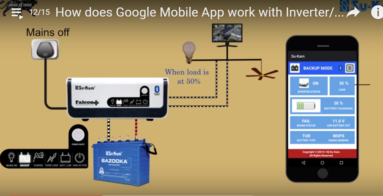


Power Solutions-SOLUÇÕES EM NOBREAKS E ESTABILIZADORES

REVISTA POTÊNCIA ENG. HILTON MORENO

INFORDATA INGENIERIA DE LA INFORMATICA PERÚ


REDE LINKEDIN ARMANDO CAVERO :http://br.linkedin.com/pub/armando-cavero-miranda/9/659/113


Prof Gustavo Castelo Branco, Prof. Slobodan Cuk e Prof Armando Cavero Miranda -BRAZILIAN POWER ELECTRONICS CONFERENCE -Cobep/Spec - 2015-CEARA-BRASIL


WEBSITES IMPORTANTES
CALCUL D'UN PETIT TRANSFORMATEUR SECTEUR
Petits transformateurs Calcul abaques et réalisation (10 VA à 500 VA)
BUREAU D´ETUDE ELETRONIQUE INFORMATIQUE
TUTORIAL PSPICE8-MICROSIM


 JOSIL ARTISTA PLASTICO FORTALEZA CEARA BRASIL AV.HERACLITO GRAÇA 41 TEL(85)32542378