AUTOR DO BLOG ENG.ARMANDO CAVERO MIRANDA SÃO PAULO BRASIL

"OBRIGADO DEUS PELA VIDA,PELA MINHA FAMILIA,PELO TRABALHO,PELO PÃO DE CADA DIA,PROTEGENOS DO MAL"

"OBRIGADO DEUS PELA VIDA,PELA MINHA FAMILIA,PELO TRABALHO,PELO PÃO DE CADA DIA,PROTEGENOS  DO MAL"

“SE SEUS PROJETOS FOREM PARA UM ANO,SEMEIE O GRÂO.SE FOREM PARA DEZ ANOS,PLANTE UMA ÁRVORE.SE FOREM PARA CEM ANOS,EDUQUE O POVO.”

“Sixty years ago I knew everything; now I know nothing; education is a progressive discovery of our own ignorance. Will Durant”

segunda-feira, 12 de fevereiro de 2018

UPS ONLINE 10KVA- GRUPO DE PROCESSAMENTO DE ENERGIA E CONTROLE(GEPEC) UNIVERSIDADE FEDERAL CEARA-BRASIL


UPS SINGLE PHASE ONLINE 10KVA DESENVOLVIDO NO GEPEC GPEC- GRUPO DE PROCESSAMENTO DE ENERGIA E CONTROLE DA UNIVERSIDADE FEDERAL DE CEARÁ EM PARCERIA COM A MICROSOL.,TENHO ORGULHO E SATISFAÇÃO DE TER TRABALHADO EM VÁRIOS TRABALHOS COMO ENG.DE PESQUISA DA MICROSOL.

O Grupo de Processamento de Energia e Controle (GPEC), criado em 1995, é ligado ao Departamento de Engenharia Elétrica (DEE) da UFC e tem como objetivo a pesquisa e o desenvolvimento tecnológico em eletrônica de potência. O GPEC atua na proposição de soluções tecnológicas para os setores industriais e de serviço, portanto trabalha em parceria com a indústria nacional, empresas de energia elétrica e institutos de pesquisa no Brasil e no exterior. Os professores e pesquisadores do grupo têm tido atuação destacada no curso de graduação e no programa de pós-graduação em Engenharia Elétrica da UFC, contribuindo na formação e qualificação de profissionais para atuação em áreas como: Sistemas Elétricos de Potência, Eletrônica de Potência, Acionamento Industrial, Qualidade de Energia Elétrica e Aproveitamento de Fontes Renováveis de Energia.
WEBSITE DO GPEC  : http://www.gpec.ufc.br/

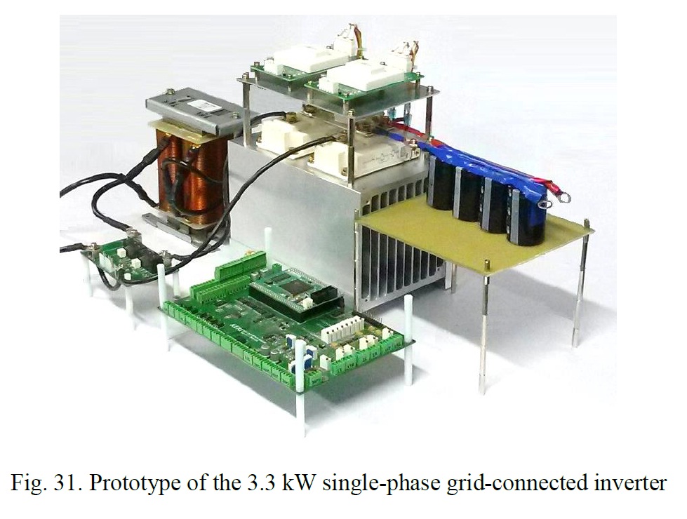
UPS SINGLE PHASE 10KVA GRUPO DE PROCESSAMENTO DE ENERGIA E CONTROLE GEPEC FORTALEZA CEARA,UM DOS MAIORES GRUPOS DE PESQUISA DE ELETRÔNICA DE POTENCIA DO BRASIL,PESSOALMENTE ME SINTO MUITO FELIZ DE TER SER PARTE DA HISTORIA VIVA DO DESENVOLVIMENTO DA ELETRÔNICA DE POTENCIA NO BRASIL,MESMO QUE HOJE POR QUESTÕES ECONÔMICAS E POLITICAS QUASE TODOS OS EQUIPAMENTOS SÃO IMPORTADOS E NOSSO DEVER TER SEMPRE NOSSA TECNOLOGIA PRÓPRIA,O PROBLEMA FUNDAMENTAL NÃO E O PROJETO,O PROBLEMA FUNDAMENTAL E A PRODUÇÃO EM ESCALA UNIVERSAL PARA TER PREÇO E SER COMPETITIVOS NO MERCADO,NESTE REQUISITO CHINA ATUALMENTE DOMINA A PRODUÇÃO EM ALTÍSSIMA ESCALA O QUAL E UM GRANDE DESAFIO PARA TODOS.

POWER ELECTRONICS PROF. YONGSUG SUH -PART10-AC-DC CONVERTER 전력전자 및 실험 전북대학교 서용석 - CHONBUCK NATIONAL UNIVERSITY - KOREA OPEN COURSEWARE PART10-


Principles of static power conversion , switching cell structure , DC-DC converter , AC-DC converter , DC-AC converter
POWER ELECTRONICS PROF. YONGSUG SUH - CHONBUCK NATIONAL 
UNIVERSITY - KOREA OPEN COURSEWARE 
PART10- AC-DC converter introduction to Switch-mode Inverter

domingo, 11 de fevereiro de 2018

Power electronics aspects for AC grid connected systems - a revision .-Wilson Komatsu- Escola Politécnica-UNIVERSIDADE DE SÃO PAULO BRASIL


Tese de Livre Docencia DocumentoTese de Livre Docencia
AutorKomatsu, Wilson (Catálogo USP)
Nome completoWilson Komatsu
E-mail E-mailUnidade da USP Escola Politécnica
Área do Conhecimento Eletrônica de Potência
Data de Defesa 2011-09-27
ImprentaSão Paulo, 2011
Banca examinadora Galvão, Luiz Cláudio Ribeiro (Presidente) Kaiser, Walter Kassick, Ênio Valmor Pomilio, José Antenor Suemitsu, Walter Issamu
Título em português
Aspectos de eletrônica de potência em sistemas ligados à rede de corrente alternada - uma revisão.Palavras-chave em português Eletrônica de potência

Resumo em português Vários equipamentos de eletrônica de potência são conectados à rede de corrente alternada (CA), para os mais diversos fins, como conversão de energia, filtragem de corrente e tensão, correção de reativos da rede CA etc. Este trabalho apresenta uma revisão não abrangente, refletindo a experiência do autor, sobre tais equipamentos. São discutidos aspectos de aplicações, modelamento de equipamentos e componentes, controle de conversores, implementação e testes. A abordagem é realizada com o uso de publicações do autor com seus associados, de modo que não se apresenta aqui proposta inédita, mas sim uma integração de conhecimento adquirido.

Título em inglês
Power electronics aspects for AC grid connected systems - a revision
.Palavras-chave em inglês Power electronics
 Resumo em inglês Many power electronics equipment are connected to the alternating current (AC) grid in order to provide different functions, as energy conversion, current and voltage filtering, AC reactive power compensation etc. This work shows an abridged revision, reflecting author's experience, on such equipment. Application aspects, equipment and components modeling, converter control, implementation and tests are discussed. The approach is done using published works from the author with his associates, therefore no unpublished proposal is presented, but instead the acquired knowledge is exposed.

LINK ORIGINAL: http://www.teses.usp.br/teses/disponiveis/livredocencia/3/tde-21052012-181653/es.php
DOWNLOAD: http://www.teses.usp.br/teses/disponiveis/livredocencia/3/tde-21052012-181653/publico//TeseLivreDocenciaWilsonKomatsu.pdf


Wilson Komatsu currently works at the Departamento de Engenharia de Energia e Automação Elétricas (PEA) (POLI), University of São Paulo. Wilson does research in Electronic Engineering and Electrical Engineering. Their most recent publication is 'Digital Control for PLLs Based on Moving Average Filter: Analysis and Design in Discrete Domain.

sábado, 3 de fevereiro de 2018

A Novel Analog Circuit Design for Maximum Power Point Tracking of Photovoltaic Panels - Nesrine Mhiri,Abdulrahman Alahdal,Hamza Ghulman, and Anis Ammous


A Novel Analog Circuit Design for Maximum Power Point Tracking of Photovoltaic Panels Nesrine Mhiri,1 Abdulrahman Alahdal,2 Hamza Ghulman,2 and Anis Ammous1,2 

1Power Electronics Group (PEG), National School of Engineers of Sfax, University of Sfax, Sfax, Tunisia 2DEE, Umm Al Qura University, Makkah, Saudi Arabia
 Advances in Power Electronics Volume 2017 (2017), Article ID 9409801, 9 pages
 https://doi.org/10.1155/2017/9409801

 1. Introduction
 Currently, the production of domestic and industrial energy is based, in large part, on a limited resource: oil. Oil sources are becomingmore andmore rare, while the energy demands of the world rise continually. Since this formof energy covers a large part of the current energy production, it is necessary to find another solution to take over.The imposed constraint is to use an energy source that is economical and less polluting because the protection of the environment has become an important point [1–3]. The search for alternative energy resources has therefore become a crucial issue these days. Many scientific researches have been carried out, not only in the field of nuclear energy production, but also in the sector of unlimited energy sources, such as wind power generation and energy transformation. In the latter case, the design, optimization, and realization of photovoltaic systems are topical issues since they lead to a better exploitation of solar energy [2]. These photovoltaic powers generating systems can be operated in different places: electrification of isolated sites, installation in buildings or direct connection to network of electricity, and so on. A major problem with PV systems is to realize transfer of maximum power from PV generator to load. For several years, manyMPPT controlmethods have been developed and implemented, like Fuzzy Logic Method [4–7], perturbation and observation (P&O) method [5, 6, 8], and Incremental Conductance (Inc.Con.) method [7, 9–11].These techniques are generally complex and expensive to implement [4, 9, 12]. They differ in several aspects like complexity, range of effectiveness, cost, convergence speed, implementation hardware, required sensors, and popularity, plus other respects. However, these techniques are digital implementation. Alternatively, the MPPT can be implemented by analog circuits [13–15]. The potential benefit from analog solution is that theMPPT can be integrated withDC-DCcontroller such that “plug and play” can be expected for many low power PV applications. In fact, integration of certain functions into a normal PWM controller chip is the most desirable way for special applications to reduce the implementation complexity and system cost. In this paper, a new analog MPPT technique suitable for PV system applications is presented and validated by simulations.

LINK ORIGINAL:https://www.hindawi.com/journals/ape/2017/9409801/
DOWNLOADhttp://downloads.hindawi.com/journals/ape/2017/9409801.pdf

quarta-feira, 31 de janeiro de 2018

Inductor Design Method of DCM Interleaved PFC Circuit for 6.6-kW On-board Charger Bong-Gi You*, Byoung-Kuk Lee* and Dong-Hee Kim - Department of Electrical and Computer Engineering, Sungkyunkwan University, Korea


Inductor Design Method of DCM Interleaved PFC Circuit for 6.6-kW On-board Charger Bong-Gi You*, Byoung-Kuk Lee* and Dong-Hee Kim


Corresponding Author: Department of Electrical Engineering, Chonnam National University, Korea. (kimdonghee@jnu.ac.kr) * Department of Electrical and Computer Engineering, Sungkyunkwan University, Korea. (bongary91@gmail.com, bkleeskku@skku.edu) Received: April 6, 2017; Accepted: July 17, 2017

 Abstract – Because the on-board charger (OBC) is installed in electric vehicles (EVs), high power density is regarded as a key technology. Among components of the OBC, inductors occupy more than 30% of the total volume. Thus, it is important to reduce the volume and the weight of inductors while maintaining thermal stability. Discontinuous conduction mode (DCM) can satisfy these requirements; however, only a few studies have adopted the DCM operation for OBCs because of the large inductor current ripple. In this paper, a design process is proposed for application of the DCM operation to OBCs. In order to analyze the inductor losses accurately, a numerical formula for the inductor current ripple is deduced based on a detailed analysis. Two inductors are fabricated using several ferrite cores and powder cores taking into consideration the inductor size, inductor losses, and temperature rise. In order to verify the analysis and design process, experimental results are presented that show that the designed inductors satisfy the requirements of the OBCs

LINK VIEW FULL TEXT
http://www.jeet.or.kr/LTKPSWeb/pub/pubfpfile.aspx?ppseq=1896

sábado, 20 de janeiro de 2018

High Frequency Isolated Power Conversion from Medium Voltage AC to Low Voltage DC Shishuo Zhao - Virginia Polytechnic Institute and State


High Frequency Isolated Power Conversion from Medium Voltage AC to Low Voltage DC 
Shishuo Zhao - Virginia Polytechnic Institute and State 

 Abstract
 Modern data center power architecture developing trend is analyzed, efficiency improvement method is also discussed. Literature survey of high frequency isolated power conversion system which is also called solid state transformer is given including application, topology, device and magnetic transformer. Then developing trend of this research area is clearly shown following by research target. State of art wide band gap device including silicon carbide (SiC) and gallium nitride (GaN) devices are characterized and compared, final selection is made based on comparison result. Mostly used high frequency high power DC/DC converter topology dual active bridge (DAB) is introduced and compared with novel CLLC resonant converter in terms of switching loss and conduction loss point of view. CLLC holds ZVS capability over all load range and smaller turn off current value. This is beneficial for high frequency operation and taken as our candidate. Device loss breakdown of CLLC converter is also given in the end. Medium voltage high frequency transformer is the key element in terms of insulation safety, power density and efficiency. Firstly, two mostly used transformer structures are compared. Then transformer insulation requirement is referred for 4160 V application according to IEEE standard. Solid insulation material are also compared and selected. Material thickness and insulation distance are also determined. Insulation capability is preliminary verified in FEA electric field simulation. Thirdly two transformer magnetic loss model are introduced including core loss model and litz wire winding loss model. Transformer turn number is determined based on core loss and winding loss trade-off. Different core loss density and working frequency impact is carefully analyzed. Different materials show their best performance among different frequency range. Transformer prototype is developed following designed parameter. We test the developed 15 kW 500 kHz transformer under 4160 V dry type transformer IEEE Std. C57.12.01 standard, including basic lightning test, applied voltage test, partial discharge test. 500 kHz 15 kW CLLC converter gate drive is our design challenge in terms of symmetry propagation delay, cross talk phenomenon elimination and shoot through protection. Gate drive IC is carefully selected to achieve symmetrical propagation delay and high common mode dv/dt immunity. Zero turn off resistor is achieved with minimized gate loop inductance to prevent cross talk phenomenon. Desaturation protection is also employed to provide shoot through protection. Finally 15 kW 500 kHz CLLC resonant converter is developed based on 4160V 500 kHz transformer and tested up to full power level with 98% peak efficiency.

 LINK WEB : https://vtechworks.lib.vt.edu/bitstream/handle/10919/74969/Zhao_S_T_2017.pdf?sequence=1

terça-feira, 16 de janeiro de 2018

Small-Signal Modeling and Controller Design of a Grid-Connected Inverter for Solid State Transformer-Bo-Gyeong Kim Department of Electrical and Computer Engineering ULSAN NATIONAL INSTITUTE OF SCIENCE AND TECHNOLOGY


Design of a Grid-Connected Inverter for Solid State Transformer -Bo-Gyeong Kim 
Department of Electrical and Computer Engineering ULSAN NATIONAL INSTITUTE OF SCIENCE AND TECHNOLOGY 

 Abstract
 A single-phase grid-connected inverter for solid state transformer (SST) is presented. This work is aimed at the modeling and the design of control schemes for the inverter. In this thesis, a small-signal model for the grid-connected inverter with modified bipolar pulse width modulation method is developed. Small-signal analysis allows to predict the stability and dynamics of the inverter. Based on theoretical analysis, controllers are designed to improve dynamics and to guarantee stability of the system. A high power factor and low harmonics are desirable in transmission system to improve the efficiency of the utility line. The current controller of the single-phase grid-connected inverter has sinusoidal reference to achieve power factor correction (PFC) and harmonics suppression. Proportional-integral (PI) scheme is widely used to control the power converter. The PI controller has the infinite gain at dc so it is suitable to track the dc reference. However, it is not good for tracking sinusoidal reference due to its finite gain at ac. The proportional-resonant (PR) controller which introduces large gain at specific frequency can track the sinusoidal reference without steady-state error but the error remains in step input response. The proportional-integral-resonant (PIR) controller has the advantage of both tracking the sinusoidal reference and removing the steady-state error for the step input. In this thesis, PIR controller is proposed for current control and design procedure for the PIR controller is presented. In addition, the voltage controller is needed to regulate the dc link voltage. The voltage controller is designed to improve the audio-susceptibility and the output impedance characteristics. The dynamics and stability of the inverter system is analyzed. The proposed small-signal model and controllers are verified by PSIM simulation and experiments.

LINK
http://ocean.kisti.re.kr/downfile/volume/kiee/DHJGII/2017/v66n1/DHJGII_2017_v66n1_40.pdf

LINK
http://www.mediafire.com/file/jbms2kqjx158cb9/SMALL_MODELING_GRID_CONVERTER.pdf

domingo, 14 de janeiro de 2018

EE640 - ELETRÔNICA BÁSICA II PROF ELNATAN CHAGAS FERREIRA FACULDADE DE ENGENHARIA ELÉTRICA E COMPUTAÇÃO-FEEC-UNICAMP-BRASIL


EE640 - ELETRÔNICA BÁSICA II
 Esta disciplina tem por objetivo o estudo de circuitos eletrônicos, como sejam amplificadores a transistores, circuitos com amplificadores operacionais, realimentação, resposta freqüência, etc. No final da disciplina os alunos devem ser capazes de dimensionar, projetar e implementar circuitos eletrônicos baseados nos circuitos estudados na cadeira.

 Pré-Requisitos: EE410 EE530/ EE530 F589. Os alunos devem ter conhecimentos sólidos dos seguintes tópicos: componentes eletrônicos básicos (resistências, condesadores e bobinas), semicondutores (diodos, transistores TBJ e FET), modelos de transistores bipolares e MOSFET, análise básica de circuitos (Lei das Malhas, lei dos nós, etc.) e transformada de Laplace.

EMENTA DETALHADA
 Para uma melhor visualização do andamento desta disciplina mostramos abaixo, com maior detalhe, os assuntos abordados, com as respectivas horas e referência bibliográfica. Tópicos NºHoras Bib.
 1)Revisão dos Modelos Diodos, transistores BJT e FET 4 [2]
 2)Análise de circuitos com um transistor (BJT) e FET Polarização DC e Análise em Configurações Básicas 8 [2]
 3)Análise de circuitos com dois transistores (BJT) e FET Conexões em cascata, Cascode, Darlinton, Quasi-Darlington, Par realimentado, Par Diferencial, Espelho de corrente. 8 [2]
 4)Resposta em freqüência Resposta em freqüência de um amp. de um estágio, Resposta em freqüência de um amp. de múltiplos estágios. 8 [4]
 5)Amplificadores Operacionais Tipos de Opamp, Estrutura básica de um Opamp FV, Opamp básicos, Opamp ideal e real, Característica de Opamp., Modelos. 10 [4]
 6)Circuitos com Amplificadores Operacionais Amp. não Inversor, Amp. Inversor, Amp. Diferença, Amp Somador, Integrador, Diferenciador, Aplicações não Lineares. 6 [4]
 7)Realimentação Equação da realimentação ideal, Efeitos da realimentação, Configurações, Configurações práticas e efeito de carregamento, Realimentação em um simples estágio. 8 [4]
 8)Circuitos Integrados Processos básicos em fabricação de CI, fabricação de circuitos em tecnologia bipolar, Dispositivos ativos em tecnologia bipolar, componentes passivos em tecnologia bipolar, fabricação de circuitos em tecnologia MOS, Dispositivos ativos em tecnologia MOS, componentes passivos em tecnologia MOS.

DOWNLOADS E AULAS

Aula 1Aula 2Aula 3Aula 4
Aula 5Aula 6Aula 7Aula 8
Aula 9Aula 10Aula 11Aula 12
Aula 13Aula 14Aula 15Aula 16
Aula 17Aula 18Aula 19Aula 20
Aula 21Aula 22Aula 23Aula 24*
PROF. ELNATAN CHAGAS FERREIRA


Physics, UFC, 1981, MSc. In Electrical Engineering, UNICAMP, 1984. Ph.D. In Electrical Engineering, UNICAMP, 1991. Livre Docência In Electronic Instrumentation, UNICAMP, 2001. Professor since 1985 in Microelectronics and Electronic Department -DEMIC. Responsible for Department's Laboratory of Sensors and Instrumentation.

LINK ORIGINAL
http://www.demic.fee.unicamp.br/~elnatan/index.html
LINK COMPLETO DE ARCHIVOS CLASES Y EXAMENES
http://www.demic.fee.unicamp.br/~elnatan/ee640/

sábado, 6 de janeiro de 2018

High Efficiency Power Converter for Low Voltage High Power Applications - Morten Nymand - DTU Electrical Engineering Technical University of Denmark

Nymand High Efficiency Power Converter for Low Voltage High Power Applications 
Author:Morten Nymand
Supervisor:Michael A. E. Andersen
 DTU Electrical Engineering Technical University of Denmark Ørsteds Plads Building 349 DK-2800 Kgs. Lyngby Denmark
 Publishing date: January 2010
Classification: Public Edition: 1st Edition
Note: This thesis is submitted in partial fulfillment of the requirements for obtaining the PhD degree at the Technical University of Denmark. Copyright: Morten Nymand, 2010

 Abstract
The topic of this thesis is the design of high efficiency power electronic dc-to-dc converters for high-power, low-input-voltage to high-output-voltage applications. These converters are increasingly required for emerging sustainable energy systems such as fuel cell, battery or photo voltaic based energy systems.

Applications include systems for emergency power back-up (UPS), de-centralized combined heat and power systems, traction applications such as hybrid electrical vehicles, forklift trucks and special applications such as low emission power generation for truck and ship containers, and remote power generation for light towers, camper vans, boats, beacons, and buoys etc.
In chapter 2, a review of current state-of-the-art is presented. The best performing converters achieve moderately high peak efficiencies at high input voltage and medium power level. However, system dimensioning and cost are often determined by the performance at the system worst case operating point which is usually at minimum input voltage and maximum power. Except for the non-regulating V6 converters, all published solutions exhibit a very significant drop in conversion efficiency at minimum input voltage and maximum output power.
 In chapter 3, a detailed analysis of dominant loss factors in high power converters for low voltage applications is presented. The analysis concludes that:
 Power transformers for low voltage high power, if properly designed, will have extremely low leakage inductance.
  If optimally designed, boost converters will be much more efficient than comparable buck type converters for high power low voltage applications.  The use of voltage clamp circuits to protect primary switches in boost converters is no longer needed for device protection. On the other hand, they will dramatically increase power losses. Moreover, if a converter is properly designed, primary side voltage clamp circuits will not even work in low voltage high power converters.
  Very high conversion efficiency can be achieved. Peak efficiency of 98% and worst case minimum efficiency of 96.8% are demonstrated on a 1.5 kW converter.

 In chapter 4, the ability to - and challenges involved in - scaling of power converters for low voltage applications in the power range of 1-10 kW are analyzed. The analysis concludes that power MOSFETs needs to be paralleled extensively to scale power level to 10 kW. Maintaining fast current switching and reliable current sharing is essential. Further, the high ac-current carrying loop on the converter primary side will become increasingly difficult to scale due to fundamental issues such as physical size of components and penetration depth in copper.
Finally in chapter 5, a new method for partial paralleling of multiple primary power stages in isolated boost converters is presented. Maximum benefit of scaling in terms of higher efficiency and lower cost is preserved by only paralleling primary switches and the critical high ac-current loop. Dynamic current sharing is inherently guaranteed between parallel power stages. The principle can be applied to all isolated boost type converters and, in principle, an unlimited number of power stages can be paralleled. Feasibility and operation of the new topology are demonstrated on a dual 3 kW and a quad 10 kW prototype converter. Measured peak efficiency is 98.2% and worst case minimum efficiency is between 96.5% and 96.9%.

LINK
http://orbit.dtu.dk/fedora/objects/orbit:82166/datastreams/file_4650370/content

segunda-feira, 1 de janeiro de 2018

Laboratório de Microrredes Inteligentes na UNIVERSIDADE FEDERAL DE SANTA CATARINA-BRASIL (uGridLab)


VÍDEO INSTITUCIONAL


Laboratório de Microrredes Inteligentes na UFSC (uGridLab)-UNIVERSIDADE FEDERAL DE SANTA CATARINA ,NOVAS TECNOLOGIAS,NOVOS PARADIGMAS .

LINK DO LABORATORIO
http://ugridlab.paginas.ufsc.br/