AUTOR DO BLOG ENG.ARMANDO CAVERO MIRANDA SÃO PAULO BRASIL

"OBRIGADO DEUS PELA VIDA,PELA MINHA FAMILIA,PELO TRABALHO,PELO PÃO DE CADA DIA,PROTEGENOS DO MAL"

"OBRIGADO DEUS PELA VIDA,PELA MINHA FAMILIA,PELO TRABALHO,PELO PÃO DE CADA DIA,PROTEGENOS  DO MAL"

“SE SEUS PROJETOS FOREM PARA UM ANO,SEMEIE O GRÂO.SE FOREM PARA DEZ ANOS,PLANTE UMA ÁRVORE.SE FOREM PARA CEM ANOS,EDUQUE O POVO.”

“Sixty years ago I knew everything; now I know nothing; education is a progressive discovery of our own ignorance. Will Durant”

terça-feira, 23 de fevereiro de 2010

IR Thermography


The design of reliable power electronic converter systems depends
partly on an accurate knowledge of the power stage component
operating temperatures under extremes of load and input voltage.
This article demonstrates how the use of modern infra-red (IR)
imaging techniques can significantly enhance the design qualification
process and show up potential problems at a very early stage in
the product development cycle. The techniques highlighted are
applicable to any power converter system or electronic product
where knowledge of component operating temperatures is
important for reliability modelling and lifetime prediction.
By Dr. Iain Mosely, Technical Director, Converter Technology Ltd

One of the main limiting factors affecting the power capability and
reliability of any electronic power converter system is the operating
temperature of key power stage components. Excessive component
temperature will reduce product operating lifetimes and could result
in early field returns. Traditionally, thermocouples are used to
measure the operating temperature of components.
Whilst thermocouples can give very accurate temperature
measurements, they do have a few potential drawbacks:
• Thermocouples can pick up noise if they are placed near to power
components with high dv/dt switching waveforms present and this
can give misleading measurement results.
• Thermocouples will sink a small amount of heat away from the device
they are attached to. For physically small components, this can lead
to measurement inaccuracy.
• Thermocouples are often only placed on components which are
expected to show a reasonable temperature rise. Other components
may not be monitored at all and this could lead to problems if a
design error leads to a high operating temperature on a component
which hasn’t been monitored.

IR thermography is a non-contact measurement technique which
uses a calibrated infrared camera to form athermal image of the
system under test.
As the measurement technique is noncontact, the noise susceptibility
and heatsinking effects sometimes encounteredwith thermocouples
are no longer an issue. More importantly, an entire PCB can be imaged
which immediately shows up any hotspots or problem components that
may have otherwise been overlooked.

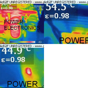
An example thermographic image ofa power converter is shown
in Figure 1.The power converter used has an issue with a snubber
TVS diode which can be seen to be running at >150°. Using the
thermal imaging camera is this example would immediately alert
the designer to a potential problem with the PSU before it reaches
the pre-production or production stage. The real value of thermography
in power electronic design is this ability to rapidly flag potential
design issues at a very early stage.

Infrared Imaging of Power Electronic Converters


Thermal management of electronic devices and packaging is important when dealing with high-voltage high-power systems as excessive device heating can have a catastrophic affect on the performance of a system and can lead to premature device and system failure. Therefore, it is necessary to accurately assess and characterize the thermal performance of power electronic components.
The use of thermal imaging equipment (infrared cameras) allows us to see beyond the visible into the invisible infrared. Our eyes are capable of detecting visible radiation but not infrared radiation. Infrared radiation is a form of electromagnetic radiation as are: visible light, radio waves, ultraviolet, and X-rays. Infrared radiation is longer in wavelength than visible light and is classified in a different waveband. Although few objects emit in the visible waveband, in the infrared waveband all objects emit. It is only that it cannot be seen with the physical eye. An infrared camera, therefore, becomes the "infrared eyes" into the infrared world. Infrared radiation is absorbed and emitted by objects. Absorptivity is the measure of how well an object or material absorbs radiation. Emissivity is the factor that correlates to the ability of an object to radiate infrared energy. In the way that visible light reflects off a mirror, infrared radiation reflects off many objects. For example, infrared radiation reflects clearly off metals such as aluminum. The fact that metals are good reflectors makes them poor emitters.
Manufacturing and process engineers boost efficiency and cut costs by turning to machine-vision systems like automated infrared (IR) imaging. The technique is being used in a host of industrial production applications, including process monitoring and control, quality assurance, asset management, and machine-condition monitoring.


segunda-feira, 22 de fevereiro de 2010

Simulation, Design and Construction of High Voltage DC Power Supply at15 kV Output Using Voltage Multiplier Circuits


Simulation, Design and Construction of High Voltage DC Power Supply at
15 kV Output Using Voltage Multiplier Circuits

N. Mariun, D. Ismail, K. Anayet, N. Khan and M. Amran
School of Electrical System Engineering, Northern Malaysia University College of Engineering
01000 Kangar, Perlis, Malaysia.

Abstract: This study describes the details of high voltage DC power supply whose output voltage is 15
kV. In this study, we review the major aspects of the design of voltage multiplier circuits and
constructed a prototype power supply based on simulation, design and implementation of the hardware
works in the laboratory. Its simulation works done by using EMTDC PSCAD and PSPICE software.
Experimental results are presented to verify the simulation results.


INTERNATIONAL JOURNAL OF PLASMA SCIENCE AND ENGINEERING


domingo, 21 de fevereiro de 2010

Physics of Free Energy Device

Physics of Free Energy Device
There is no energy crisis in the world. Instead, there is amnesia in the minds of the scientists and the physicists.

Dipole (Anti)Gravity, Magnetic Gravity, true Gravitomagnetism


Dr. Eue Jin Jeong

Extended Static Gravity Potential
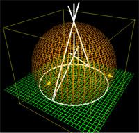
Although it should be obvious up to this point of the discussion regarding dipole gravity, I would like to present the succinct mathematical form of the static portion of the extended gravity potential for the rotating hemispherical (in general, longitudinal axially asymmetric) object, for the sake of our younger generation.

EVENT:2010:TOP 10 EXOTIC FREE ENERGY Technologies for Earth Transformation Conference

THE TOP TEN EXOTIC FREE ENERGY TECHNOLOGIES REVEALED, with Sterling D. Allan. Beyond the conventional renewables such as solar, wind, geothermal, tide, and wave energy technologies, there are a plethora of fascinating and promising technologies that could be more reliable, less expensive, and even cleaner. These more exotic technologies include electromagnetic overunity systems in the tradition of Nikola Tesla that "harness the wheelwork of nature", cold fusion, magnet motors, water power, plasma, and zero point energy devices, to name a few. To use a childbirth analogy, "this baby is crowning", nearly ready to emerge. Sterling D. Allan is the founder of a dozen-plus organizations whose functions range from preparedness and alternative energy development and promotion to defining, teaching and researching better ways to live as a society. Organizations he has been the driving force behind include: FreeEnergyNews.com, the New Energy Congress, Pure Energy Systems Wiki, Pure Energy Systems News, and PureEnergySystems.com. He has established a positive reputation in maintaining a news service and an extensive directory of energy solutions that are friendly to the environment.


Directory:Perendev Power Developments Pty (Ltd)

sábado, 20 de fevereiro de 2010

Tesla - Electricidad Inalambrica

Nikola Tesla biography 1/7

Nikola Tesla's BiographyJuly 10, 1856. born in Smiljan, a village near Gospić 1862. started primary school 1862. - 1863. The Milutin Tesla's family moved to Gospić; Nikola finished his primary school as well as first three grades of so-called "lower Real-Gymnasium" 1870. - 1873. Finished last three grades of "higher Real-Gymnasium" in Rakovac, near Karlovac; professor Martin Sekulić, who taught maths and physics, had a decisive influence on Nikola 1873. - 1874. Suffered from cholera for nine months; his father agreed that he can enrol polytechnic school 1874. - 1875. One-year recovery in Tomingaj, near Gračac 1875. - 1878. Studied at Polytechnic School in Graz ; spent twelve hours in reading and learning; excellent marks ; pointed out to professor Poeschl that the Gramme's engine was not perfect without a commutator and brushes December 1878. Went to Maribor, unemployed Tags: nikola tesla genius smiljan gospic lika croatia hrvatska serb Science energy Coil croat croatian signs hrvatski .