quarta-feira, 28 de fevereiro de 2024
quinta-feira, 22 de fevereiro de 2024
Programa de Estágio da Lacerda Sistemas de Energia- Apoio a Inovação e Tecnologia em Eletrônica de Potência
VIEW FULL VIDEO : globoplay.globo.com/v/12224781/
Recentemente, o Programa de Estágios Lacerda, através do nosso talentoso colaborador Guilherme Almeida, foi destaque no Jornal Nacional. Em entrevista, Guilherme compartilhou como o estágio na Lacerda foi uma peça fundamental em sua jornada acadêmica e profissional. Hoje, graças ao seu desempenho e comprometimento, ele faz parte de nossa equipe como colaborador efetivo, contribuindo ainda mais para o sucesso e crescimento contínuo da empresa.
Não perca a chance de fazer parte da nossa equipe! Visite nosso site:
https://mla.bs/6019b11c para mais informações.
Research on the simulation of a new compensation strategy for dynamic voltage correction device Xuewei Zhang1,2*, Xiaojuan Sun1 , Tianfeng Wang3 -1 School of Electronic and Information Engineering, Xi’an Technological University, Xi’an, 710021, China
Research on the simulation of a new compensation strategy for dynamic voltage correction device
Xuewei Zhang1,2*, Xiaojuan Sun1, Tianfeng Wang3
1School of Electronic and Information Engineering, Xi’an Technological University,
Xi’an, 710021, China
2School of Mechanical and Electrical Engineering, Xi’an Technological University,
Xi’an, 710021, China
3Xi'an Kaitian electrical reliability laboratory Co., Ltd, Xi’an, 710077, China
*Corresponding author’s e-mail: xueweizhang163@163.com
Abstract.
A new detection and compensation method for voltage sag is proposed. Dynamic
voltage correction device(DVCD) is the most effective device to solve voltage sag. Based on
the shortcomings of the traditional compensation strategy, the compensation characteristics of
the compensation strategy are analyzed systematically. This paper proposes a new
compensation method based on the traditional minimum energy compensation method, which
uses different minimum energy methods for different sags, namely zero active power exchange
and minimum energy exchange. Through Simulink to establish the simulation model of
minimum energy method, and make simulation analysis. The simulation results show that the
method can achieve the minimum output active power while ensuring the compensation effect,
which proves the feasibility and effectiveness of the method. This method can make full use of
energy storage of equipment and has high economic benefits.
VIEW FULL TEXT:
domingo, 18 de fevereiro de 2024
IX Congresso Brasileiro de Eletrônica de Potência COBEP2007 – Blumenau- SC - Brasil
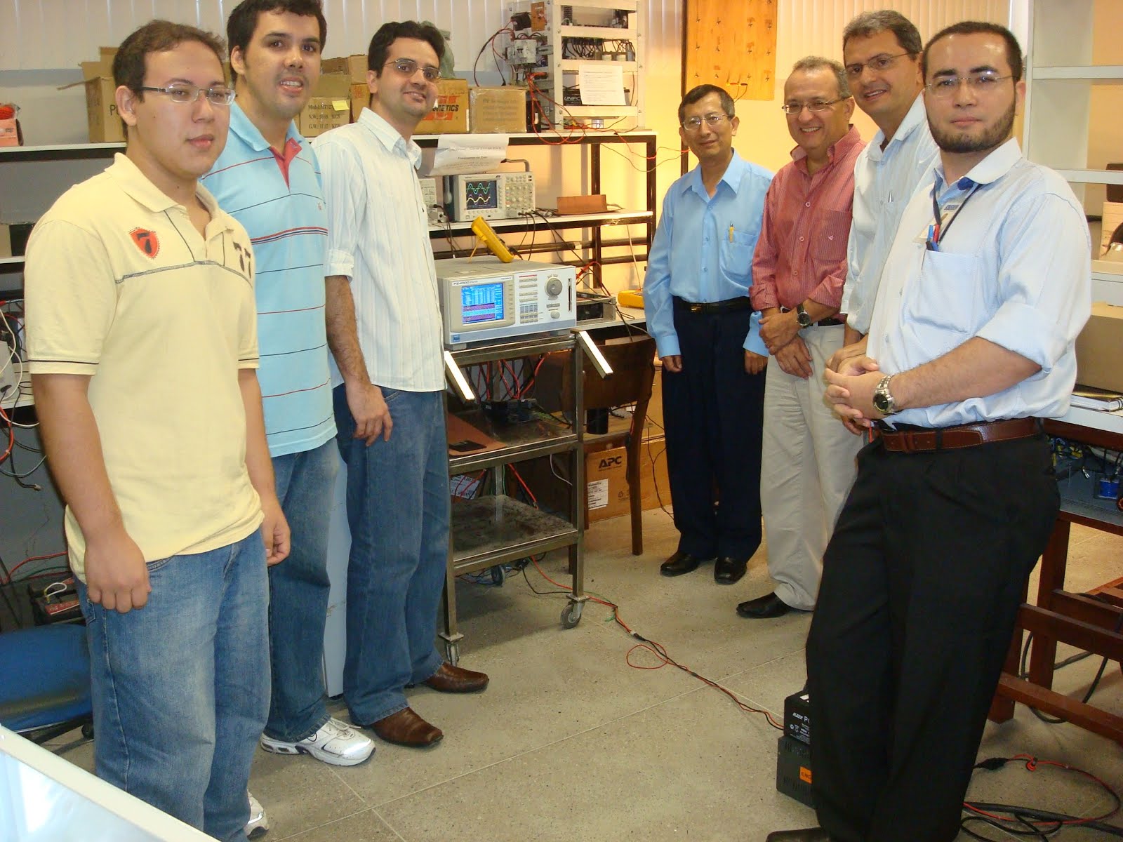
LEMBRANÇA DO IX Congresso Brasileiro de Eletrônica de Potência COBEP2007 – Blumenau- SC - Brasil na fotografia com meu distinguidos colegas Professores da Universidade Federal do Ceará - Engenharia Elétrica eles são conhecidos a nivel mundial pelas suas pesquisas e publicações a nivel mundial em Eletrônica de Potência.
sexta-feira, 16 de fevereiro de 2024
Total volume evaluation of high-power densitynon-isolated DC–DC converters withintegrated magnetics for electric vehicles-Wilmar Martinez1,2 , Camilo Cortes1, Masayoshi Yamamoto3, Jun Imaoka4, Kazuhiro Umetani5
Total volume evaluation of high-power density non-isolated DC–DC converters with integrated magnetics for electric vehicles
ISSN 1755-4535
Received on 3rd March 2017
Revised 29th June 2017
Accepted on 21st July 2017
E-First on 25th August 2017
doi: 10.1049/iet-pel.2017.0157
www.ietdl.org
Wilmar Martinez1,2 , Camilo Cortes1, Masayoshi Yamamoto3, Jun Imaoka4, Kazuhiro Umetani5
1Universidad Nacional de Colombia, Bogota, Colombia
2Aalto University, Espoo, Finland
3Nagoya University, Nagoya, Japan
4Kyushu University, Fukuoka, Japan
5Okayama University, Okayama, Japan
E-mail: whmartinezm@unal.edu.co
Abstract
One of the main problems in electric vehicles is the volume of their electrical systems because their bulky
components carry additional mass and high cost to the total system. On this topic, interleaving-phases and magnetic coupling
techniques have been reported as effective methods for increasing the power density of the DC–DC converters that work
between the storage unit and the motor inverter. In that sense, a volume assessment of these topologies would provide a better
understanding of the problems to be faced when an electric power train is designed. In this paper, a volume modelling
methodology is introduced with the purpose of comparing four different DC–DC converters: Single-Phase Boost, Two-Phase
Interleaved with non-coupled inductors, Loosely Coupled Inductor (LCI), and Integrated Winding Coupled Inductor (IWCI). The
analysis considers the volume of magnetic components, power devices (conventional and next-generation), cooling devices and
capacitors. The methodology can be used as a part of an optimization procedure to minimize the volume of DC–DC converters.
Conclusively, LCI and IWCI were found effective to miniaturize power converters with a power density of 8.4 W/cc and 9.66
W/cc, respectively. Moreover, a maximum efficiency of 98.04% and 97.61% was obtained for a 1kW LCI and IWCI prototypes,
respectively.
VIEW FULL TEXT:
quarta-feira, 14 de fevereiro de 2024
Projeto de Filtro LC para Volume Mínimo Considerando as Perdas no Conversor e os Tempos de Vida dos Capacitores Aplicado a uma UPS de Dupla Conversão-Pedro C.Bolsi1,2, Edemar O.Prado1,2, João M.Lenz1,3, Hamiltom C.Sartori1, José RenesPinheiro1
Revista Eletrônica de Potência (Brazilian Journal of Power Electronics), published by SOBRAEP
PROJETO DE FILTRO LC PARA VOLUME MÍNIMO CONSIDERANDO AS
PERDAS NO CONVERSOR E OS TEMPOS DE VIDA DOS CAPACITORES
APLICADO A UMA UPS DE DUPLA CONVERSÃO
Pedro C. Bolsi 1,2, Edemar O. Prado 1,2, João M. Lenz 1,3, Hamiltom C. Sartori 1, José Renes
Pinheiro 1,2
1Universidade Federal de Santa Maria, Santa Maria – RS, Brasil
2Universidade Federal da Bahia, Salvador – BA, Brasil
3Universidade Federal da Integração Latino-Americana – PR, Brasil
e-mail: pcbolsi@gmail.com, edemar.prado@ufba.br, jlenz@ieee.org, hamiltomsar@gmail.com, jrenes@gepoc.ufsm.br
- Pedro C. BolsiUniversidade Federal da Bahia, Salvador – BA, Brasilhttps://orcid.org/0000-0002-6425-1795
- Edemar O. PradoUniversidade Federal da Bahia, Salvador – BA, Brasilhttps://orcid.org/0000-0002-4438-032X
- João M. LenzUniversidade Federal da Integração Latino-Americana – PR, Brasilhttps://orcid.org/0000-0002-7349-4828
- Hamiltom C. SartoriUniversidade Federal de Santa Maria, Santa Maria – RS, Brasilhttps://orcid.org/0000-0002-7451-7411
- José Renes PinheiroUniversidade Federal de Santa Maria, Santa Maria – RS, Brasilhttps://orcid.org/0000-0001-9686-8004
Resumo–Este trabalho apresenta uma metodologiade projeto de filtrosLCanalisando o seu impactono conversor. Leva-se em consideração as perdas e ovolume do filtro, as perdas e o volume do conversor, ea vida útil dos capacitores. A metodologia é baseadana execução do dimensionamento físico (partnumbers,volume) e estimativa das perdas em cada parte dosistema, empregando modelos analíticos validadosexperimentalmente. A partir de um perfil de missão edas perdas nos capacitores, a vida útil é estimada para oscapacitores dos filtrosLCe barramento CC do conversor.O projeto é otimizado em função das perdas no sistema,volume total, e vida útil dos capacitores. Apontam-se osbenefícios da priorização de cada uma destas métricas.
VER TEXTO COMPLETO:
Control convertidor dc-ac de 100kW Proyecto Final de Grado-Autor: Juan Carlos Olives Camps Tutor: Joan Rocabert Delgado 10/12/2013 Grado en Ingeniería Eléctrica – Escola d’Enginyers de Terrassa – UPC
Resumen
Este proyecto desarrolla un estudio y diseño de un inversor trifásico que trabaja como
fuente de corriente conectado a red. Tanto a nivel de hardware (los elementos físicos
necesarios para su funcionamiento) como el desarrollo del software de control.
A nivel de hardware se explicará la función de los componentes y estudiará la necesidad
y las variables que determinan su dimensionado. Al mismo tiempo, el uso de
convertidores de potencia conectados a red requiere la implementación de un adecuado
sistema de filtrado. Es por este motivo que en este proyecto se dedicarán unas líneas al
diseño de este.
A nivel de software se pretende desarrollar una evolución, en cuanto a complejidad, del
sistema de control así como las etapas necesarias para el desempeño de su función. Se
presentarán los resultados obtenidos mediante la simulación de los circuitos y los
resultados experimentales del testeo de un inversor real.
Las etapas de control y software se realizarán para un inversor de 100kW, mientras que
el dimensionado de los elementos de hardware se llevará a cabo para uno de 50kW.
Finalmente, los ensayos realizados sobre el inversor serán realizados controlando un
convertidor de 10kW.
Abstract
This project develops the study and design of a three-phase inverter connected to the
grid working as a current source. Both hardware level (the physical elements necessary
for its operation) as the development of the control software.
About the hardware level, the role of the components and the need for their existence
will be explained as the variables that determine its sizing. The use of power converters
connected to the grid requires the implementation of a suitable filtering system. For this
reason, a few lines of this project will try to explain the filter design.
The study about de software level will try to develop an evolution, in terms of
complexity, of the control system as well as the steps needed to carry out its work. The
results obtained by simulating the circuits and experimental results of testing will be
presented and compared.
Control stages and software will be performed for a 100kW inverter; however, the
sizing of the hardware elements will be calculated for one of 50kW. Finally, testing of
the inverter will be carried out by controlling a 10kW converter.
VIEW FULL TEXT:
segunda-feira, 12 de fevereiro de 2024
Assinar:
Postagens (Atom)









 JOSIL ARTISTA PLASTICO FORTALEZA CEARA BRASIL AV.HERACLITO GRAÇA 41 TEL(85)32542378