AUTOR DO BLOG ENG.ARMANDO CAVERO MIRANDA SÃO PAULO BRASIL

"OBRIGADO DEUS PELA VIDA,PELA MINHA FAMILIA,PELO TRABALHO,PELO PÃO DE CADA DIA,PROTEGENOS DO MAL"

"OBRIGADO DEUS PELA VIDA,PELA MINHA FAMILIA,PELO TRABALHO,PELO PÃO DE CADA DIA,PROTEGENOS  DO MAL"

“SE SEUS PROJETOS FOREM PARA UM ANO,SEMEIE O GRÂO.SE FOREM PARA DEZ ANOS,PLANTE UMA ÁRVORE.SE FOREM PARA CEM ANOS,EDUQUE O POVO.”

“Sixty years ago I knew everything; now I know nothing; education is a progressive discovery of our own ignorance. Will Durant”

domingo, 15 de março de 2015

DSP-Based Control for Parallelism of Three-Phase Voltage Source Inverter Telles B. Lazzarin, Member, IEEE, and Ivo Barbi, Fellow, IEEE Power Electronics Institute (INEP), Department of the Electrical Engineering (EEL), Federal University of Santa Catarina (UFSC), Florianópolis , Brazil


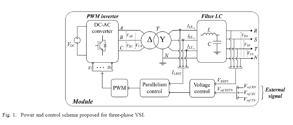
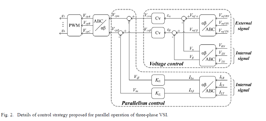
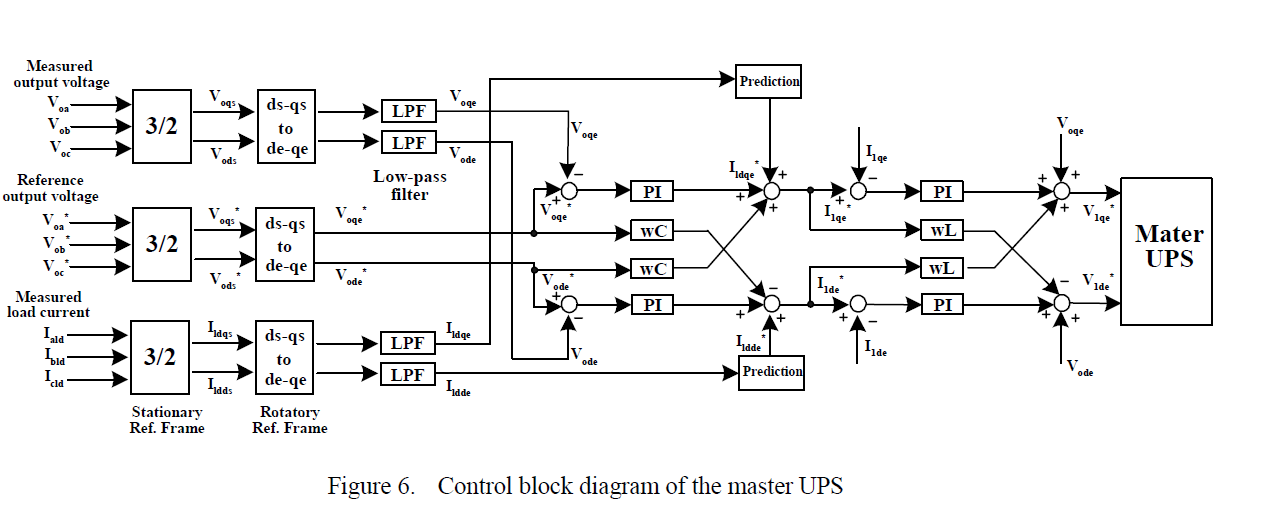
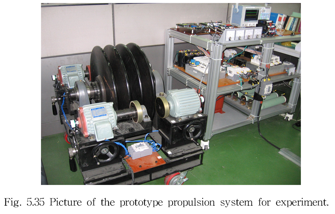
Abstract—This paper describes a theoretical and experimental study on a control strategy for the parallel operation of three-phase voltage source inverters (VSI), to be applied to UPS. The proposed control system for each inverter consists of two main loops, which both use instantaneous values. The first (parallelism control) employs the feedback of the inductor currents from the output filter to modify the input voltages of the same filter and thereby control the power flow of each VSI to the load. Additionally, the second loop (voltage control) is responsible for controlling the output voltages of the LC filter, which coincides with the output voltages of the VSI. The proposed control strategy ensures the proper sharing of the load current and avoids current circulation among the inverters during transient and steady-state operation. The VSI and the proposed control strategy are analyzed in an orthogonal stationary frame, and as a result, simple and effective models were achieved. The proposed control system was digitally implemented in a TMS320F2812 DSP and was verified through experimental results with a 10 kVA prototype, which has the parallel operation of two three-phase VSIs.

II. INTRODUCTION
 ININTERRUPTIBLE power supply (UPS) devices are employed to feed critical loads which, at high power values, utilize a three-phase system. Moreover, inmany applications the total load consists of a set of single and three-phase loads, which requires the employment of three-phase UPS, capable of feeding all types of load. In addition, critical loads also require a power supplywith high-reliability and redundancy that can be obtained with the parallel-connection ofUPSs.As iswell-known, the parallelism of UPS is a problem related to the parallel operation of voltage source inverters (VSIs). The parallel operation of three-phase VSIs has a greater complication due to the complexity and the greater number of variables involved in a three-phase system. Recent publications in the literature [1]–[3] broach this problem and they point out that there is still a need for new solutions to the parallelism of three-phase VSIs. It is also well-known that the parallel operation of VSIs requires a control system to ensure proper operation of the structure. A traditional solution is the strategy based on the frequency and voltage droop [4]–[18]. This strategy controls the average active and reactive power flow from the VSI to the load and it does not require communication among the inverters. It provides increased reliability and redundancy but it has errors associated with load sharing, poor transient response, reduced voltage regulation and it does not control the division of the harmonic currents [1], [3]. In the literature there are interesting studies reported [8], [9], [11], [18]–[22] which minimize the disadvantages, in most cases addressing single-phase systems. On the other hand, there are strategies related to communication, such as central control [23]–[25], master-slave control [26]–[29] and distributed control [2], [3], [30], [25]. These strategies are most effective in terms of load sharing, but high reliability and redundancy are not available due to the communication between units. In recent years, these strategies have been based on the instantaneous current control [2], [3], [24], [34], [35], in which the parallelism control receives information on the instantaneous current supplied by all units. Good transient response and the appropriate load sharing among VSIs, including the harmonics of load current, are advantages introduced by instantaneous control. The evolution of these strategies is associated with the use of microcontrollers, DSP and FPGA in power converters [36]–[44]. The digital control provides the means to propose new solutions to complex problems as in the parallel operation of three-phase voltage inverters. In this context, this paper proposes a distributed control strategy for the parallel operation of three-phase VSIs. Each VSI has its own control unit, responsible for regulating the output voltages and ensuring its parallel operation.


A Master and Slave Control Strategy for Parallel Operation of Three-Phase UPS Systems with Different Ratings Woo-Cheol Lee, Taeck-Ki Lee Sang-Hoon Lee, Kyung-Hwan Kim, Dong-Seok Hyun In-Young Suh-Department of Electrical Engineering HanKyong National University-Seoul, Korea


quinta-feira, 12 de março de 2015

AEG POWER SOLUTIONS NEW TRAINING DATES FOR 2015 AVAILABLE - POWER SUPPLIES SYSTEM


The Service Training Center in Belecke serves as the basis for professional training in technical service support. Owing to the long years of experience in training at AEG Power Solutions, we have been able to continually improve our competence. We are considered nowadays to be the training facility for service experts. We hold training sessions in all AEG PS technologies and our trainees achieve a high degree of expertise. Target groups for our training sessions include staff from service departments, testing fields, application engineering, R&D and sales. Prerequisite for trainees is that they are skilled electrical.
LINK
http://www.aegps.com/en/services/training/

domingo, 8 de março de 2015

Development of a Compact 750KVA Three-phase NPC Three-level Universal Inverter Module with Specifically Designed Busbar Jun Wang, Binjian Yang, Jing Zhao, Yan Deng, Xiangning He College of Electrical Engineering Zhejiang University Hang Zhou, China


Abstract—This paper presents the bus bar design of a 750kVA three-phase Neutral Point Clamped three-level universal inverter module (PEBB) of high power density. ANSOFT Q3D is used in comparative evaluation for three types of multi-layer bus bar structures and a novel low inductive laminated configuration with divided connections is proposed for this inverter modules. Combined with specially arranged snubber capacitors distribution, reduced voltage overshoots across IGBTs at turned-off and lower loss within the electrolytic capacitors are achieved without any RC snubbers, along with optimized high frequency current equalization. The stray inductance of the bus bar is simulated as a contrast to the test results. Feasibility and improved performance are confirmed by experiments.

sábado, 7 de março de 2015

34- The flyback converter 14 28 UNIVERSITY OF COLORADO BOUDER

Performance Improvement of PWM Converter-Inverter System for AC Supplied Electric Train -HYUNGCHUL KIM -CHUNGBUK NATIONAL UNIVERSITY


ABSTRACT
Domestically in 1994, both Gwacheon and Bundang line used the GTO converter/inverter system instead of the resistance control system, which started active research on AC supplied vehicle.[3] Addition to this, introduction of high-speed railway vehicles such as KTX and tilting train has developed interest about PWM converter-inverter system and its control method.[9] PWM converter which converts AC power into DC power has been used to maintain the sinusoidal current waveform and unity power factor in AC side. This means that the AC current controller of PWM converter has to produce very low AC current tracking error and no phase delay even though the load changes abruptly.[10-17] The PWM converter system with feedback controller is generally constructed with double feedback loop, which consists of an inner AC current-feedback loop and an outer DC voltage-feedback loop.[7][22] These feedback loops are usually designed with PI controller, but the close interconnection between the loops complicates the frequency analysis to the design controller. When a digital controller is used, the control performance is limited to a certain value due to the low sampling rate. Therefore, the system characteristics depend on various situation, and the gain tuning of each PI controller has been basing on trial and error method conventionally considering switching frequency, sampling frequency, parameter variation, and etc. This research proposes a robust digital current controller for a single phase AC/DC PWM converter in electric train under two main considerations. One is that overall system keeps very low AC current tracking error without any phase delay over the different load conditions, and the other is that the digital controller is designed at a fixed sampling rate. First, we design a continuous-time controller for a continuous-time plant and then discretize the controller with the given sampling frequency. This kind of process has some disadvantages because its fidelity depends on the sampling rate and the discrete method, but it has sufficient and valuable design method in developing continuous-time linear systems. The error-space feedback control scheme to carry out the robust AC current tracking is used, which is well known as an analytic state-feedback method to give a controller the ability to track a non-decaying input perfectly and to reject a non-decaying disturbance such as a sinusoidal input. And to achieve the time response requirements, the characteristic ratio assignment (CRA) is introduced, which has the ability to deal directly with the overshoot and speed of step response in an all-pole system with arbitrary order.[25] This method is based on certain relationships between the coefficients of characteristic polynomial and the transient responses. The CRA design formulates a model matching method whose reference model is selected from a target polynomial. In this paper, the state feedback gains are determined by the CRA instead of the pole-placement method.
LINK
http://www.mediafire.com/view/sxc1dk8mmveiyzp/Performance_Improvement_of_PWM_Converter-Inverter_System_for_AC_Supplied_Electric_Train.pdf

ON THE PERSPECTIVES OF WIDE-BAND GAP POWER DEVICES IN ELECTRONICS BASED POWER CONVERSION FOR RENEWABLE SYSTEMS SAMUEL VASCONCELOS ARAUJO KASSEL UNIVERSITY


LINK ORIGINAL
http://www.uni-kassel.de/upress/online/frei/978-3-86219-486-5.volltext.frei.pdf

Analysis and Comparison of Power Electronic Converters with Electronic Isolation Por Kazanbas, Mehmet


LINK
https://books.google.com.br/books?id=jn_NBgAAQBAJ&lpg=PA153&ots=qPcwif2Tyz&dq=THESIS%20GERMANY%20POWER%20ELECTRONICS%20CONVERTER%20KASSEL%20UNIVERSITY&hl=pt-BR&pg=PP1#v=onepage&q&f=false

quinta-feira, 5 de março de 2015

"TEORÍA DE CONJUNTOS Y TEMAS AFINES" - Seymour Lipschutz


SURFANDO EN LA INTERNET ENCONTRE ESTE LIBRO EN LA PAGINA WEB
http://matealdia.blogspot.com.br/2012/04/teoria-de-conjuntos-y-temas-afines.html

LINK  skydrive   : http://sdrv.ms/Qmz8Yu

A Study on the Design of 300W Power Factor Correction using Interleaving Method-TAE-WOO KIM DEPT. OF ELECTRICAL ENGINEERING GRADUATE SCHOOL CHANGWON NATURAL UNIVERSITY


ABSTRACT
Generally, critical conduction mode(CRM) boost PFC converter used low power level and continuous conduction mode(CCM) boost PFC converter is used in medium or high power application. Critical conduction mode boost PFC converter can be used in medium or high power application by using interleaving technical. Interleaved critical conduction mode boost PFC converter can reduce current ripple for higher system reliability and smaller buck capacitor and EMI filter size. In this paper, The design of 300W PFC preconverter using interleaving method which can improve light-load efficiency and have many advantage, is presented.