terça-feira, 7 de fevereiro de 2017
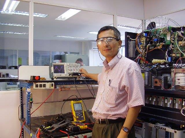
Control Method of 3-Phase AC/DC PWM Converter for DC distribution using SECOND ORDER GENERALIZED INTEGRATOR (SOGI)- FREQUENCY LOCKED LOOP ( FLL )-SHIN KI WRONG
Control Method of 3-Phase AC/DC PWM Converter for DC distribution using SECOND ORDER GENERALIZED INTEGRATOR (SOGI)- FREQUENCY LOCKED LOOP ( FLL )-SHIN KI WRONG
DEPARTMENT OF ELECTRICAL AND COMPUTER ENGINEERING
SUNGKYUNKWAN UNIVERSITY
segunda-feira, 6 de fevereiro de 2017
Zero dead-time PWM method for reducing THD in offshore wind power 3-level inverter - KAN YONG -PROGRAM ENERGY SYSTEM ENGINEERING - SUNGKYUNKWAN UNIVERSITY
AAAA
To prevent the short circuit dead time is required because it can happen the short circuit due to a difference between rising time and falling time ocurred in power semiconductor swith. However dead time cause the distortion and THD increase of output current,it is major cause of malfunction by distorted output current and high THD.
In this paper,circuit of 3-level NPC inverter and characteristic of operation is analyzed.Also switching methods wich make the switching pattern of Zero Dead-time PWM for decreasing THD and optimization method is proposed. Proposed Zero Dead -time PWM method is explained on the basis of theoretic analysis,hardware is set for applying the proposed method.
LINK
http://www.mediafire.com/file/5k85lybur3tzl9o/PWM_DEAD_TIME_2017.pdf
sábado, 4 de fevereiro de 2017
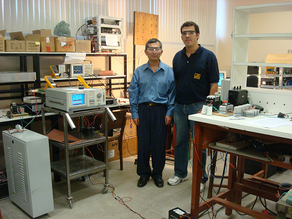
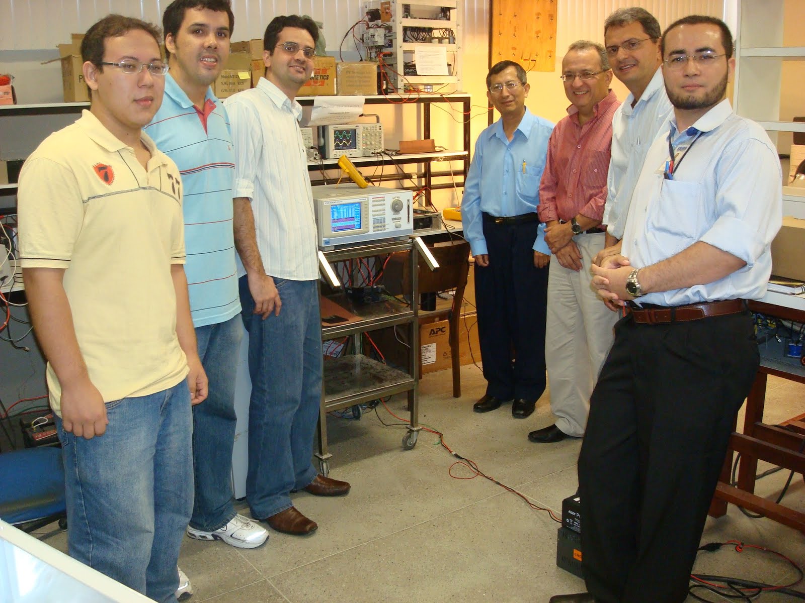
Engenharia Elétrica e a Pós-graduação na Universidade Federal do Ceará - PROFESSOR PAULO PRAÇA ( CHEFE DO DEPARTAMENTO DE ENGENHARIA ELÉTRICA DA UNIVERSIDADE FEDERAL DE CEARÁ)-BRASIL
PESSOALMENTE EU TRABALHEI DE 2006 A 2012 NA EMPRESA MICROSOL HOJE APC-SCHNEIDER,A EMPRESA MICROSOL TINHA UMA ESTREITA PARCERIA COM O PROGRAMA DE ENGENHARIA ELÉTRICA DA UNIVERSIDADE FEDERAL DE CEARÁ,ESPECIALMENTE COM O PROGRAMA DE MESTRADO E DOUTORADO,O NÍVEL ACADÊMICO DOS ALUNOS,PROFESSORES E LABORATÓRIOS SÃO EXCELENTES,EXISTE AMBIENTE PARA A PESQUISA E DESENVOLVIMENTO.
quinta-feira, 2 de fevereiro de 2017
Design and Testing of Voltage Source Inverter and Motor Control System for Electric Vehicle - Lars Helge Oplopisal - Norwegian University of Science and Technology - Department of Electric Power Engineering
Design and Testing of Voltage Source
Inverter and Motor Control System for
Electric Vehicle
Lars Helge Opsahl
Master of Energy and Environmental Engineering
Supervisor: Lars Einar Norum, ELKRAFT
JULY 2015
Submission date: July 2015
Norwegian University of Science and Technology
Department of Electric Power Engineering
Abstract
With fast rotating permanent-magnet motors and compact battery storage units, the high performance motorsport community has, in recent years, started to utilize the quick response and high torque of electrical drivetrain solutions. By recovering energy, braking into a corner, for then to utilize the same energy, boosting out again, the electrical machine gives increased performance even for the fastest racing cars. The purpose of the work presented in this Master’s thesis is to develop and produce the power electronics and motor control system needed to control such an electric machine, where the final product is used to drive a fully electric prototype racing car. The thesis presents the conceptual work, design choices, prototyping, testing and development of a 2-level voltage source inverter and motor control system. The voltage source is a battery accumulator energy storage unit, while the machine is a three-phase permanent-magnet motor. The voltage source inverter is based on insulated-gate bipolar transistors (IGBTs), controlled by a motor control system called field oriented control. On command from the driver’s throttle, the motor control system generates the required stator currents, giving the wanted output torque, supplied from the voltage source of the battery accumulator. The inverter is the connecting interface between the power source, and the rotating machinery. With the amount of energy and power needed to drive a racing car, safe and reliable operation is important. To ensure the safety of the driver and operating personnel, the system and its safety features have been through extensive testing in a laboratory setup and on the race tracks. In the system development process, simulation and modelling tools have been applied to investigate different solutions and technologies. These tools have also been used to design the electric circuits, program code and mechanical design needed for the system. The final product is installed in a racing car and shows great performance.
LINK ORIGINAL COMPLETE THESIS
https://brage.bibsys.no/xmlui/handle/11250/2368215
DIRECT LINK
https://brage.bibsys.no/xmlui/bitstream/handle/11250/2368215/13287_FULLTEXT.pdf?sequence=1&isAllowed=y
Design of a 48 V three-phase inverter For automotive applications -FREDRIK FÜRST - Department of Energy and Environment CHALMERS UNIVERSITY OF TECHNOLOGY Gothenburg, Sweden 2015
Design of a 48 V three-phase inverter: For automotive applications
Master's thesis in Electric Power Engineering
Fredrik Furst
Department of Energy and Environment
Chalmers University of Technology
Abstract
This project presents a design and construction of a three-phase inverter,
drive circuit and dc-link capacitor bank. The inverter should be able to
supply an electrical machine with 48 V and 250 A. Initial calculations and
simulations were made to get some base for the ordering of hardware. The
inverter board consists of six MOSFETs in parallel for each phase and the
PCB itself is made of aluminum to enable a thermal substrate technique.
The inverter PCBs are mounted on an aluminum frame where liquid runs
between them to cool the inverter. The drive circuit is controlled with a
dSPACE system and the tests are made with a load consisting of cables
and iron powder cores. Temperatures are measured with PT100 sensors
for the water and an infrared camera for the surfaces.
Two di erent MOSFETs were investigated, one with higher switching
losses and one with higher conduction losses. The two inverters were tested
on an RL load and the cooling system picked up around 270 W at a phase
current of 150 Arms. Theoretical calculations, performed with measured
parameters, represents the temperature measurements well. The thermal
resistance between the case and the sink in the inverter, R cs, is measured
to around 0:15 [K=W].
Index Terms: Capacitor bank, cooling system, drive circuit, dSPACE,
inverter, MOSFET, thermal evaluation.
LINK ORIGINAL COMPLETE THESIS
http://publications.lib.chalmers.se/records/fulltext/224623/224623.pdf
Assinar:
Postagens (Atom)




 JOSIL ARTISTA PLASTICO FORTALEZA CEARA BRASIL AV.HERACLITO GRAÇA 41 TEL(85)32542378