AUTOR DO BLOG ENG.ARMANDO CAVERO MIRANDA SÃO PAULO BRASIL

"OBRIGADO DEUS PELA VIDA,PELA MINHA FAMILIA,PELO TRABALHO,PELO PÃO DE CADA DIA,PROTEGENOS DO MAL"

"OBRIGADO DEUS PELA VIDA,PELA MINHA FAMILIA,PELO TRABALHO,PELO PÃO DE CADA DIA,PROTEGENOS  DO MAL"

“SE SEUS PROJETOS FOREM PARA UM ANO,SEMEIE O GRÂO.SE FOREM PARA DEZ ANOS,PLANTE UMA ÁRVORE.SE FOREM PARA CEM ANOS,EDUQUE O POVO.”

“Sixty years ago I knew everything; now I know nothing; education is a progressive discovery of our own ignorance. Will Durant”

sábado, 25 de agosto de 2018

An Electrical Power System for CubeSats Presented by: Benjamin C. de V. Sheard Dept. of Electrical and Electronics Engineering University of Cape Town


An Electrical Power System for CubeSats
Presented by:
Benjamin C. de V. Sheard
Supervisor:
Mr. Samuel I. Ginsberg
Dept. of Electrical and Electronics Engineering
University of Cape Town
Submitted to the Department of Electrical Engineering at the University of Cape
Town in partial fulfilment of the academic requirements for a Master of Science
degree in Electrical Engineering.
ABSTRACT
The advent of CubeSats has provided a platform for relatively low-budget programmes to realise space missions. In South Africa, Stellenbosch University and the Cape Peninsula University of Technology have impressive space programmes and have been involved in numerous successful satellite launches. A number of CubeSat projects are currently in progress and commercial-grade Attitude Determination and Control Systems (ADCS), and communications modules, are being developed by the respective universities. The development of a CubeSat-compatible Electrical Power System remains absent, and would be beneficial to future satellite activity here in South Africa. In this thesis, some fundamental aspects of electronic design for space applications is looked at, including but not limited to radiation effects on MOSFET devices; this poses one of the greatest challenges to space-based power systems. To this extent, the different radiation-induced effects and their implications are looked at, and mitigation strategies are discussed. A review of current commercial modules is performed and their design and performance evaluated. A few shortcomings of current systems are noted and corresponding design changes are suggested; in some instances these changes add complexity, but they are shown to introduce appreciable system reliability. A single Li-Ion cell configuration is proposed that uses a 3.7 V nominal bus voltage. Individual battery charge regulation introduces minor inefficiencies, but allows isolation of cells from the pack in the case of cell failure or degradation. A further advantage is the possibility for multiple energy storage media on the same power bus, allowing for EPS-related technology demonstrations, with an assurance of minimum system capabilities. The design of each subsystem is discussed and its respective failure modes identified. A limited number of single points of failure are noted and the mitigation strategies taken are discussed. An initial hardware prototype is developed that is used to test and characterise system performance. Although a few minor modifications are needed, the overall system is shown to function as designed and the concepts used are proven.
LINK
https://open.uct.ac.za/bitstream/handle/11427/20101/thesis_ebe_2015_sheard_benjamin_charles_de_villiers.pdf?sequence=1

sábado, 18 de agosto de 2018

Research on a GaN HEMT On-Board Charger for Electric Vehicles Thesis for the degree of Doctor of Philosophy Guoen Cao-Dept. of Electronic Systems Engineering Hanyang University


Research on a GaN HEMT On-Board Charger for Electric Vehicles 
 Thesis for the degree of [Doctor of Philosophy Guoen Cao Hanyang University Graduate School

 ABSTRACT
Research on a GaN HEMT On-Board Charger for Electric Vehicles Guoen Cao Dept. of Electronic Systems Engineering The Graduate School Hanyang University With an accelerating global energy crisis and deteriorating environmental problems, electric vehicle (EV) technologies have attracted growing interest due to their reduced fuel usage and greenhouse emissions. The battery charger plays a critical role for the acceptance and development of EVs. Because a battery is generally used as the main power source, a high conversion efficiency, high power density, and lightweight on-board-charger (OBC) is needed in order to maximize the energy utilization. Gallium nitride based high electron-mobility transistors (GaN HEMTs) are potential candidates as next-generation power switching devices due to the enormous potential use in the applications of high frequency, high temperature, and high output power, in particular of battery charger applications. Although much progress has been achieved in the development of GaN HEMTs, a few important issues such as current collapse effects should be evaluated before wide deployment is possible. Since evaluating performance in power semiconductors and selecting the optimal topologies are important steps in the design and development of power electronics circuits, this thesis is concerned with the performance evaluation of the new GaN HEMTs and the design of an isolated OBC that uses GaN HEMTs to achieve high efficiency for future applications in EVs. GaN HEMTs suffer from current collapse effect in operation regions, which leads the dynamic on-resistance to increase when a high voltage is applied to the transistor. In order to measure the dynamic on-resistance and evaluate the current collapse effect of newdesigned GaN HEMTs, a novel soft-switching measurement circuit based on synchronous buck topology is introduced. To apply high-voltage and high-current stresses to the device without additional spikes and oscillation, the resonance technique has been employed. As a result, the proposed circuit can produce sufficient high frequency switching voltage and current stresses equal to or greater than that would be found in real power applications to the devices with general equipment. In order to achieve accurate measurement of onresistance under high frequency switching operations and eliminate the saturation of conventional methods, an active voltage clamp circuit is developed. A prototype circuit has been built. Experiments conducted under extreme conditions have been carried out. The simulation and experimental results confirm the validity of the proposed circuit. After evaluating characteristics of the new-designed GaN HEMTs, an isolated high efficiency on-board battery charger using these new power devices is presented. The OBC has a two-stage structure, where the first stage is an interleaved boost AC-DC power factor correction (PFC) converter and the second stage is a full-bridge LLC resonant converter. As the GaN HEMT has very low gate threshold voltage, a high-speed isolated gate driver circuit with negative voltage has been developed for the efficient operation of the two stages For the GaN-based PFC converter, circuit modeling and the power stage design method are discussed in detail. To keep high power factors and high dynamic performance under a wide input and output range, a fuzzy logic PI current controller and a non-linear voltage controller based on the circuit model are proposed. A 1.5 kW hardware prototype is developed and a maximum system efficiency of 97.5% is measured while operating with the switching frequency of 200 kHz. The results also show a considerable increase in system efficiency and superior performance of the proposed converter compared to the conventional control methods.
For the full-bridge LLC resonant converter, a novel design method for lithium battery charger applications is proposed. According to the charging characteristics, three operating points are selected for the optimum design. A thorough analysis of design procedure is performed, considering the performance evaluation of GaN HEMTs. A 1.5 kW prototype circuit was built, with an output voltage range of 250 V to 420 V. Experimental results show that high efficiency of 95.9% is achieved by using GaN HEMTs and it has resulted in 0.9% improvement compared to the conventional silicon-based converter. In order to implement digital control and control the two-stage in an effective way, a two-core floatingpoint DSP is employed for the OBC. Keywords Electric vehicles, battery charger, GaN HEMT, evaluation circuit, interleaved PFC, fuzzy logic control, soft-switching, LLC resonant converter

SEPOC 2018 - 11th SEMINAR ON POWER ELECTRONICS AND CONTROL-Santa Maria RS,BRASIL 21-24 October 2018


SEPOC 2018 - 11th SEMINAR ON POWER ELECTRONICS AND CONTROL-Santa Maria RS,BRASIL 21-24 October 2018
 The seminar's objective is to provide interaction between academia and industry to discuss the latest cutting-edge technologies on Power Electronics and Control and their applications. In 2018, the conference is themed on Industry Applications. Authors are invited to submit original research work according to the topics listed below.
 Power Electronics topologies and design
 Modeling, control and design of renewable energy conversion systems
Electrical machines design, control and drives
Control theory and applications
Power systems analysis, modeling, operation and control
 Smart grid, grid protection and energy quality
Distributed energy planning, management and expansion
Efficiency, technologies and reliability of electronic equipments
 Topologies and control for smart lighting systems
 Automotive, aerospace, transportation and telecommunication systems
Automation systems and robotics
 Standards, codes and education topics on electrical engineering

LINK ORIGINAL
http://coral.ufsm.br/sepoc/sepoc2018/index.php/pt/

sexta-feira, 17 de agosto de 2018

TRANSFORMADORES FACTOR K - K-factor & Transformers


Transformadores con Clasificación del Factor K


DESCRIÇÃO

Hoy en día, en los locales de trabajo industrial, la proliferación de dispositivos de estado sólido (reactores de iluminación, sistemas de movimientos y control de motores, equipamientos de comunicaciones, y otras cargas de motorización DC) ha criado algunos relevantes problemas para ingenierías de especificaciones, contratantes y propietarios de negocios. La naturaleza no lineal de las fuentes de alimentación de modelos con conmutación por sistemas de estado sólido generan corrientes de armónicos que, a su vez, generan pérdidas adicionales, que hacen que los transformadores (algunas de estas pérdidas son profundas dentro de los bobinados y algunas son más próximas de la superficie) y los neutros del sistema se sobrecalienten y se destruyan.

Efecto de los armónicos en los transformadores en seco
Hay diversas situaciones que pueden crear condiciones para problemas de armónicos en transformadores, incluyendo la adición del equipamiento a un sistema eléctrico existente, o la adición de instalaciones de perfeccionamiento o expansiones a una fuente de potencia existente. Los transformadores con especificaciones de factor K están diseñados para reducir los efectos de calentamiento de las corrientes de armónicos creadas por cargas no lineales. La clasificación del factor K, atribuida a un transformador, es un índice da habilidad del transformador de soportar un índice armónico en su corriente da carga, permaneciendo dentro de los límites de la temperatura de funcionamiento. Una clasificación específica del factor K indica que un transformador puede suministrar, además de la salida nominal de carga en KVA, una carga de una cantidad especificada de índice armónico. En 1990, UL (Underwriters Laboratories) desarrolló el método de cálculo de clasificación del factor K para evaluar la habilidad de los transformadores en soportar los efectos de los armónicos. El factor K no significa que el transformador puede eliminar los armónicos. El test de UL está dirigido al calentamiento de los bobinados debido a las cargas no lineales generales y al sobrecalentamiento del conductor neutro.

Existen dos métodos de cálculo del factor K:
- El método UL
- El método normalizado

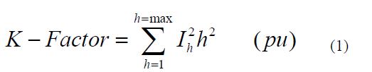
El método UL está basado en la corriente nominal eficaz "rms" del transformador. Generalmente se usa cuando la corriente eficaz es medida o mensurable y se define como:

Donde:
h = orden del armónico;
Ih(pu) = Corriente rms del armónico expresado en pu (por unidad) de la corriente nominal eficaz del transformador.

El método Normalizado está basado en la corriente fundamental de la carga. Las medidas de los armónicos están hechas frecuentemente con un analizador de armónico. La mayoría de los analizadores armónicos tienen respuestas de salida de los armónicos en pu (valores por unidad) de la corriente fundamental. Consecuentemente, el método sería usado. El método normalizado se define de la siguiente manera:

Donde:
Corriente fundamental en pu (el 1° armónico = 100%);
Un ejemplo de los dos métodos para el mismo espectro armónico de los datos es el siguiente. Para el ejemplo, suponemos que las medidas se efectuaron para obtener (pu):
Hasta el presente, las literaturas industriales y los comentarios se refieren a un número limitado de clasificaciones del factor K: K-1, K-4, K-9, K-13, K-20, K-30, K-40.

En teoría, un transformador podría estar diseñado para otras evaluaciones de factor K entre estos valores, así como para valores más elevados. Las clasificaciones generalmente referenciadas están de acuerdo con ANSI/IEEE C57.110-1986 como sigue:
K-1: Esta es la evaluación de todo el transformador convencional que fue diseñado para soportar solamente los efectos de calentamiento de las pérdidas normales y de las pérdidas adicionales por corrientes parásitas (eddy losses) resultantes de 60Hz, con el transformador cargado con corriente sinusoidal. Tal unidad puede o no estar diseñada para soportar el calentamiento adicional de los armónicos en su corriente de carga.
K-4: Un transformador con esta evaluación se diseñó para suministrar KVA nominal, sin sobrecalentamiento, a una carga constituida de 100% de frecuencia normal 60Hz, corriente sinusoidal en la fundamental, más:
- 16% de la fundamental como la 3ª corriente armónica;
- 10% de la fundamental como 5ª;
- 7% de la fundamental como 7ª;
- 5,5% de la fundamental como el 9ª;
- Porcentajes menores a través de la 25ª armónica.
El "4" indica su habilidad de soportar cuatro veces las pérdidas de corriente de “eddy” de un transformador K-1.
K-9: Un transformador K-9 puede soportar 163% de la carga armónica de un transformador clasificado como K-4.
K-13: Un transformador K-13 puede acomodar 200% de la carga armónica de un transformador clasificado como K-4.
K-20, K-30, K-40: El número más elevado de cada una de estas clasificaciones del factor K indica la habilidad de trabajar con cantidades sucesivamente mayores de índices armónicos de la carga sin sobrecalentarse.

La siguiente tabla muestra el ejemplo de cargas de factor K

CARGA - FACTOR K
Iluminación con lámparas de descargas - K-4
UPS con filtro de entrada opcional - K-4
Máquinas de soldadura - K-4
Equipamiento de calentamiento inductivo - K-4
PLCs y controles de estado sólido (otros además de drives variadores de velocidad). - K-4
Equipamientos de Telecomunicación (por ejem. PBX) - K-13
UPS sin filtros de entrada - K-13
Alimentación de receptáculos multihilos en general en áreas con instrumentos de cuidados con la salud y aulas de escuelas, etc. - K-13
Fuentes de circuitos con receptáculos multihilos para equipamientos de inspección y pruebas en sectores productivos o líneas de producción - K-13
Cargas de Equipos Servidores (Mainframe) - K-20
Drives de estado sólido para motores (Drives variadores de velocidad) - K-20
Alimentación de circuitos con receptáculos en áreas importantes de seguridad y cuartos de cirugías y recuperación de hospitales - K-20
*Reescrito con permiso de EDI Magazine

El factor K debe marcarse claramente en la placa de identificación del transformador.

Informaciones Técnicas:

Clase de temperatura: B (130°C) o F (155°C)

K-FACTOR TRANSFORMERS

K-factor rating is optionally applied to a transformer,
indicating its suitability for use with loads that draw non
sinusoidal currents. The K-factor is given by the following
equation [6, 9].

where:
h= harmonic number, Ih = the fraction of total rms load current
at harmonic number h
K-factor rated transformers have not been evaluated for use
with harmonic loads where the rms current of any singular
harmonic greater than the tenth harmonic is greater than 1/h of
the fundamental rms current.

What is K-Factor?
K-factor is a weighting of the harmonic load currents according to their effects on transformer heating, as derived from ANSI/IEEE C57.110. A K-factor of 1.0 indicates a linear load (no harmonics). The higher the K-factor, the greater the harmonic heating effects. When a non-linear load is supplied from a transformer, it is sometimes necessary to derate the transformer capacity to avoid overheating and subsequent insulation failure. The reason for this is that the increased eddy currents caused by the harmonics increase transformer losses and thus generate additional heat. Also, the RMS load current could be much higher than the kVA rating of the load would indicate. Hence, a transformer rated for the expected load will have insufficient capacity. The K-Factor is used by transformer manufacturers and their customers to adjust the load rating as a function of the harmonic currents caused by the load(s). Generally, only substation transformer manufacturers specify K-factor load de-rating for their products. So, for K-factors higher than 1, the maximum transformer load is de-rated.