quinta-feira, 23 de julho de 2020
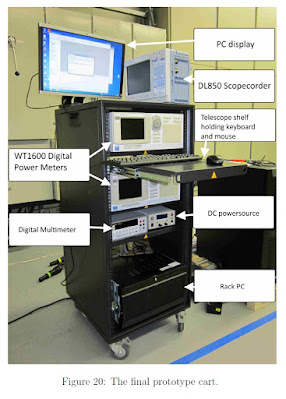
Automatic Test System for Type Tests of the Uninterruptible Power Supply by Esa Nummijoki School of Electrical Engineering Aalto University Finland
School of Electrical Engineering
Thesis submitted for examination for the degree of Master of
Science in Technology. Aalto University
Finland
Abstract of the
Master's Thesis
Testing is an essential part of product development. In UPS product development,
different tests are made every day. Testing requires large variety of measurement
instruments and other equipment such as large load systems and different kind of
test configurations. Significant number of performed tests are based on the UPS
type tests defined in the IEC-62040 standard.
Testing consumes a lot of time and that way also resources. To solve this problem,
an automatic test system for type tests is considered. The aim of this thesis was
to clarify the need for the automatic test system, and clarify requirements needed
to realize it.
The work was done by reviewing the type tests and different parts of an automatic
test system. In addition, an experimentation was made, resulting a prototype.
The prototype is able to automatically perform an indicative efficiency test for
the UPS. Furthermore, a possibility to automate the most complex type test, a
dynamic output performance test, was examined. This examination resulted a
description of the test process and LabVIEW programs, supporting the execution
of the test. However, the conclusion was that it is not sensible to automate
the test, due to the fact that it is not often performed and automating the test
requires a lot of time and resources.
The review and the experimentation proved that realization of an automatic test
system, able to perform all the type tests, requires large amount of time and
resources. Due to this, the automatic test system for type tests is not the best
solution to reduce the time and resources consumed by testing.
Keywords: Automatic Test System, Uninterruptible Power Supply, Product Development,
LabVIEW, TestStand, Prototype
Corrente de fuga em inversores monofásicos sem transformador para conexão de sistemas fotovoltaicos à rede de distribuição de energia elétrica : análise e proposta de filtro passivo integrado de modo comum e diferencial.- Ricardo Souza Figueredo-Escola Politécnica Universidade de São Paulo-USP-BRASIL
Corrente de fuga em inversores monofásicos sem transformador para conexão de sistemas fotovoltaicos à rede de distribuição de energia elétrica: análise e proposta de filtro passivo integrado de modo comum e diferencial.
Dissertação de Mestrado Autor Figueredo, Ricardo Souza (Catálogo USP)
Matakas Junior, Lourenço (Presidente)
Cavalcanti, Marcelo Cabral
Villalva, Marcelo Gradella
Resumo em português
Este trabalho apresenta um estudo sobre a corrente de fuga de modo comum em inversores monofásicos sem transformador utilizados para a conexão de sistemas fotovoltaicos (FV) à rede de distribuição de energia elétrica. O estudo se concentra em inversores do tipo fonte de tensão que empregam a topologia em ponte completa. A partir da adequada modelagem do sistema (rede, conversor e módulo fotovoltaico) identifica-se e quantifica-se a contribuição das tensões de modo comum e modo diferencial para a corrente de fuga. Conclui-se que a tensão de modo comum de alta frequência produzida pelo inversor, que depende da estratégia de modulação por largura de pulso (PWM Pulse Width Modulation) empregada, fornece a maior contribuição para produção da corrente de fuga. Esse estudo mostra que os inversores sem transformador, com topologia em ponte completa e modulação que produz tensão de saída com três níveis, necessitam de medidas adicionais para a minimização da corrente fuga quando aplicados em sistemas fotovoltaicos conectados à rede. Algumas soluções propostas na literatura para a minimização da corrente de fuga baseadas em topologias modificadas e filtros de modo comum são listadas e discutidas. Neste trabalho é proposto um filtro integrado de modo comum e modo diferencial com amortecimento passivo de baixas perdas, para minimizar a corrente de fuga produzida por um inversor monofásico sem transformador. Um exemplo de aplicação do filtro proposto é apresentado juntamente com seu procedimento de projeto, resultados de simulação e experimentais que validam a proposta. Além disso, a influência da variação da indutância da rede elétrica e da capacitância parasita do sistema fotovoltaico no comportamento do filtro proposto é analisada. A influência da variação da indutância da rede no comportamento do sistema de controle e o impacto da corrente de modo comum no projeto dos indutores do lado do conversor também são analisados.
Estudo comparativo de estratégias de controle para inversores de fontes ininterruptas de energia-Disertación de Maestría Autor Rodrigues, Álvaro Jorge-A comparative study of control strategies in inverters for Uninterruptible Power Supplies-Escola Politécnica da Universidade de São Paulo-USP-BRASIL
Resumen en portugués
Este trabalho tem como objetivo reunir, registrar, estudar e comparar as estratégias de controle utilizadas em inversores para fontes ininterruptas de energia, efetuado através de levantamento bibliográfico, englobando estratégias antigas (implementadas muitas vezes na forma analógica) e recentes (com implementação digital). É realizada comparação dos desempenhos, determinados analiticamente por modelamento e/ou por simulação computacional, entre algumas estratégias de controle. É apresentado um método para a implementação digital de um inversor monofásico para fontes ininterruptas de energia com transformador na saída. O método utilizado consiste de: Análise e modelagem dos controladores e planta, adotando-se critérios para o ajuste dos respectivos parâmetros; Simulação no modo de tempo contínuo; Roteiro da discretização para possibilitar implementação digital; Simulação em tempo discreto; Implementação em protótipo experimental. O controle é realizado com uma estratégia de múltiplas malhas, usando três malhas: uma malha interna de corrente usando controlador proporcional com compensação feedforward da perturbação da tensão de saída no controle da corrente e uma malha externa de tensão com um controlador proporcional + ressonante. Uma terceira malha de controle externa a malha de tensão é adicionada para prevenir a saturação do núcleo do transformador. O inversor é implementado através de um arranjo físico de baixa potência, possibilitando comparação dos resultados de simulação e experimentais.
Resumen en inglés
This dissertation intends to collect, register, study and compare control strategies used in inverters for uninterrupted power supplies. Older control strategies, which use analogical control, as well as contemporary ones, which use digital control, were studied. A performance comparison between some strategies is made using analytical modeling and computational simulation. It is proposed a method for implementation of digital controller for a one-phase inverter with output transformer for uninterruptible power supplies applications. The method consists on: Analysis and modeling of plant and controllers, adopting criteria for parameters adjust; Continuous time computational simulation; Discretization guide for digital implementation; Discrete time computational simulation; Experimental prototype implementation. Control uses a multiloop approach, with three control loops: An internal current loop with proportional controller and feed-forward output voltage disturbance compensation, an external voltage loop using a proportional + resonant controller, and a third external loop to prevent the saturation of the output transformer. A low power experimental setup of the inverter is implemented, allowing comparison of simulated and experimental results.
segunda-feira, 20 de julho de 2020
A Study on DC-DC Battery Charger Employing Bus Converter for Electric Vehicles by Jung, Kwang-Soon Department of Secured Smart Electric Vehicle Engineering Graduate School, Kookmin University Seoul, Korea-버스 컨버터를 적용한 전기자동차용DC-DC 배터리 충전기에 관한 연구
버스 컨버터를 적용한 전기자동차용DC-DC 배터리 충전기에 관한 연구
Doctor of Engineerintg Reques
ABSTRACT
Recently, it has become an important issue to solve the
environmental pollution problem caused by exhaust gas in the
automobile industry. Also, a lot of researches are proceeding
to develop eco-friendly vehicles such as electric vehicles.
Basically, electric vehicles are equipped with batteries and
various types of battery chargers. Among the battery chargers,
the DC-DC battery charger is powered from the high-voltage
battery for motor drive and charges the low-voltage battery
for driving electrical components. The 3.5kW DC-DC battery
charger could be developed with a phase-shift full-bridge
converter. However, a conventional phase-shift full-bridge
converter has low performance, which is resulted from both
low effective duty ratio and low transformer turn ratio, when
designed as a battery charger with a wide input/output voltage
range. To overcome these drawbacks, this paper suggests DC-DC
battery charger employing bus converter for electric vehicles.
The proposed DC-DC battery consists of the bus converter and
the pre-regulator. The bus converter produces constant input/
output voltage conversion ratio, and the pre-regulator
controls the output of the bus converter by providing a
variable link voltage to the bus converter.
The bus converter adopts the two-transformer full-bridge
converter with active clamp circuit, which operates constantly
with a maximum duty ratio of 0.5. The two-transformer
full-bridge converter simplifies the secondary-side circuit,
since two series-connected transformers replace output
inductor. Also, the two transformers can be integrated, which
provides efficient device placement solution. The bus
converter eliminates conduction loss caused by the circulating
current and achieves ZVS for the full-bridge inverter easily
without commutating inductor. In addition, the bus converter
achieves excellent ripple cancellation effects and small
output current ripple. The bus converter can adopt SR switches
with low Rds.on and reduce conduction loss on SR switches, since
the bus converter minimizes voltage stress across SR switches.
Therefore, the bus converter is very suitable for high output
current applications.
The proposed step-up/step-down converter is derived from a
two-switch buck-boost converter operating the boost leg with a
constant duty ratio of 0.5. The proposed step-up/step-down
converter can share switches with the bus converter. Also, the
proposed converter has low current ripple by using coupled
inductor.
The proposed DC-DC battery charger employs the bus converter
and the proposed step-up/step-down converter as the preregulator.
The proposed battery charger realizes high power
density by sharing switches. Also, the control of the proposed
DC-DC battery charger is simple because the battery charger
adopts PWM control.
In this paper, the operation principle of the proposed
battery charger is explained and verified by experimental
results with 3.5kW prototype. The proposed DC-DC battery
charger achieves high efficiency. The maximum measured
efficiency is 96.25%.
Key Words : Electric Vehicle, Battery Charger, Bus Converter,
Full-Bridge Converter, Two Transformer, Pre-Regulator, Coupled
inductor
ORIGINAL LINK: http://www.riss.kr/search/detail/DetailView.do?p_mat_type=be54d9b8bc7cdb09&control_no=c7106ade01d21f03ffe0bdc3ef48d419
sexta-feira, 17 de julho de 2020
Projeto P&D Estratégico Aneel - Chamada P021 UFSM-COPEL - Dis - Instalação da Planta Piloto 1- NHS SOLAR INVERSOR HIBRIDO
LINK:https://youtu.be/SerXihR-Uco
Assinar:
Postagens (Atom)








 JOSIL ARTISTA PLASTICO FORTALEZA CEARA BRASIL AV.HERACLITO GRAÇA 41 TEL(85)32542378