AUTOR DO BLOG ENG.ARMANDO CAVERO MIRANDA SÃO PAULO BRASIL

"OBRIGADO DEUS PELA VIDA,PELA MINHA FAMILIA,PELO TRABALHO,PELO PÃO DE CADA DIA,PROTEGENOS DO MAL"

"OBRIGADO DEUS PELA VIDA,PELA MINHA FAMILIA,PELO TRABALHO,PELO PÃO DE CADA DIA,PROTEGENOS  DO MAL"

“SE SEUS PROJETOS FOREM PARA UM ANO,SEMEIE O GRÂO.SE FOREM PARA DEZ ANOS,PLANTE UMA ÁRVORE.SE FOREM PARA CEM ANOS,EDUQUE O POVO.”

“Sixty years ago I knew everything; now I know nothing; education is a progressive discovery of our own ignorance. Will Durant”

terça-feira, 3 de novembro de 2020

Multi-powered UPS --Department of Electrical Engineering Graduate School, Chonnam National University Author KIM Jongcheo -Master's Thesis


 Multi-powered UPS KIM Jong Cheol Department of Electrical Engineering Graduate School, Chonnam National University (Supervised by Professor PARK Sungjun)

(Abstract)  As the society develops, load sensitive to power environment such as medical equipment, communication equipment, FA (factory automation) system and data center server is widely used, and reliability and stable supply of power system becomes more important. In particular, electrical equipment used for military purposes is not expected to have any problems in the power supply system during exhibition or operation, so it is becoming necessary to secure a reserve energy source, to duplicate the system or to make surplus system. Even if the reliability of the power supply system is high, momentary power failure due to an accident or a lightning can not be avoided, and there is also a momentary voltage drop (Sag) or a voltage rise (swell) of the power supply. Table 1 below is a definition of the power anomaly phenomenon that appears in the commercial power source shown in IEEE Std 1159TM-2009.

In case of power-sensitive load, it is necessary to prepare for system failure because it can cause fatal damage even in short-term system failure. Therefore, there is a need for an uninterruptible power supply (UPS) [1] [2] to compensate for instantaneous voltage fluctuations as well as for blackout situations.

Automotive UPS systems typically consist of a single module, such as a battery, bi-directional inverter, high-speed switch, and the UPS module is connected to the vehicle generator and critical loads. If the existing UPS system is composed of a single power source and the UPS system is composed of only one power source, it is difficult to cope with the demand of the main load in the long term only by the output of the UPS when the power source is out of power. To solve this problem, connecting several power sources to a load leads to a large increase in cost due to the connection of UPS to each power source. It is an off-line UPS system that is commonly used. The advantage of the off-line method is that when the input power is normal, there is less generation of electromagnetic waves and noise, and the power consumption is low due to high energy efficiency. In addition, it has a simple circuit configuration, high durability, low cost, and miniaturization compared to on-line. The disadvantage of off-line is that momentary power cut-off occurs in the case of power failure, and the output changes according to the input voltage change during non-operation, making it difficult to adjust the voltage and therefore it is not suitable for high-precision load. In the case of Figure 1, it is composed of a single power source, and if the UPS system consists of only one power source, it is difficult to cope with the demand of the main load in the long term only by the output of the UPS when the power source is outage. In particular, in a system having a purpose for use in a command communication terminal of a military, it is difficult to supply stable power because there are many variables in power supply.

In this paper, we propose a multi - power applied UPS system that eliminates the disadvantages of the parallel - connected power supply and has a fast switching time. The UPS system operates in the battery charging mode when the system is in normal operation and operates in the UPS mode, which is the battery discharge mode, in the event of a system failure. In such a mode switching, the follow up of the command voltage should be performed within the shortest time. Since the UPS must supply the same voltage to the load within 4ms in case of a system fault, the switching time and return time must be short when controlling the output voltage and current of the UPS, and the power failure detection time is also important. In addition, since the main loads of the UPS system are mostly time-varying and non-linear loads, it is also necessary to be able to control non-linear loads. Conventionally, a proportional integral (PI) controller has been used as a control method of such a UPS system. The PI controller has a very stable output characteristic in the steady state, but it takes a long time to reach the steady state at the time of mode change or load change due to slow acceleration. Therefore, due to the limit of the transient response characteristic of the controller, it is difficult to perform stable power supply within a short time in the case of a system fault. Also, since the gain of the PI controller affects the response characteristics, response characteristics may be slow or overshoot may occur depending on the gain value selection of the controller. Therefore, in this paper, to compensate the limitation of the proportional integral controller, the controller using the DFT with fast electrostatic sensing characteristics is applied. The control using DFT has an advantage that it can perform fast power failure detection by comparing grid voltage waveform and voltage waveform created by DFT using Schmitt trigger. Therefore, stable power supply is possible when using only PI control in mode switching in UPS system. The multi-power applied UPS system proposed in this paper is finally designed to satisfy the following conditions. In case of system fault, detection method using fast DFT is applied to the electrostatic detection in order to supply stable power to the load in a shorter time than the conventional PI control method. At this time, the switching time of mode switching was set to be less than 4 ms, which is 1/4 of the system cycle, according to KS C 4310 regulation of the uninterruptible power supply in the industry standard council. A 10kW UPS system, in which commercial voltage, vehicle generator, and auxiliary diesel generator can be connected to the proposed switchgear, was tested and validated.

LINK1:http://www.riss.kr/search/detail/DetailView.do?p_mat_type=be54d9b8bc7cdb09&control_no=8f6a0e4c451565dbffe0bdc3ef48d419

LINK2:http://www.mediafire.com/file/0bg7thkijs1736t/MULTIPOWERED+UPS.pdf/file

domingo, 25 de outubro de 2020

High Frequency (MHz) Planar Transformers for Next Generation Switch Mode Power Supplies by Radhika Ambatipudi -Mid Sweden University, Faculty of Science, Technology and Media, Department of Electronics Design.(Power Electronics)


 High Frequency (MHz) Planar Transformers for Next Generation Switch Mode Power Supplies

by Ambatipudi, Radhika

Mid Sweden University, Faculty of Science, Technology and Media, Department of Electronics Design.(Power Electronics) 2013 (English) Doctoral thesis

 ABSTRACT

 Increasing the power density of power electronic converters while reducing or maintaining the same cost, offers a higher potential to meet the current trend in relation to various power electronic applications. High power density converters can be achieved by increasing the switching frequency, due to which the bulkiest parts, such as transformer, inductors and the capacitor's size in the converter circuit can be drastically reduced. In this regard, highly integrated planar magnetics are considered as an effective approach compared to the conventional wire wound transformers in modern switch mode power supplies (SMPS). However, as the operating frequency of the transformers increase from several hundred kHz to MHz, numerous problems arise such as skin and proximity effects due to the induced eddy currents in the windings, leakage inductance and unbalanced magnetic flux distribution. In addition to this, the core losses which are functional dependent on frequency gets elevated as the operating frequency increases. Therefore, this thesis provides an insight towards the problems related to the high frequency magnetics and proposes a solution with regards to different aspects in relation to designing high power density, energy efficient transformers.

The first part of the thesis concentrates on the investigation of high power density and highly energy efficient coreless printed circuit board (PCB) step-down transformers useful for stringent height DC-DC converter applications, where the core losses are being completely eliminated. These transformers also maintain the advantages offered by existing core based transformers such as, high coupling coefficient, sufficient input impedance, high energy efficiency and wide frequency bandwidth with the assistance of a resonant technique. In this regard, several coreless PCB step down transformers of different turn’s ratio for power transfer applications have been designed and evaluated. The designed multilayered coreless PCB transformers for telecom and PoE applications of 8, 15 and 30W show that the volume reduction of approximately 40 - 90% is possible when compared to its existing core based counterparts while maintaining the energy efficiency of the transformers in the range of 90 - 97%. The estimation of EMI emissions from the designed transformers for the given power transfer application proves that the amount of radiated EMI from a multilayered transformer is less than that of the two layered transformer because of the decreased radius for the same amount of inductance.

The design guidelines for the multilayered coreless PCB step-down transformer for the given power transfer application has been proposed. The designed transformer of 10mm radius has been characterized up to the power level of 50W and possesses a record power density of 107W/cm3 with a peak energy efficiency of 96%. In addition to this, the design guidelines of the signal transformer for driving the high side MOSFET in double ended converter topologies have been proposed. The measured power consumption of the high side gate drive circuit together with the designed signal transformer is 0.37W. Both these signal and power transformers have been successfully implemented in a resonant converter topology in the switching frequency range of 2.4 – 2.75MHz for the maximum load power of 34.5W resulting in the peak energy efficiency of converter as 86.5%.

This thesis also investigates the indirect effect of the dielectric laminate on the magnetic field intensity and current density distribution in the planar power transformers with the assistance of finite element analysis (FEA). The significance of the high frequency dielectric laminate compared to FR-4 laminate in terms of energy efficiency of planar power transformers in MHz frequency region is also explored.

The investigations were also conducted on different winding strategies such as conventional solid winding and the parallel winding strategies, which play an important role in the design and development of a high frequency transformer and suggested a better choice in the case of transformers operating in the MHz frequency region.

In the second part of the thesis, a novel planar power transformer with hybrid core structure has been designed and evaluated in the MHz frequency region. The design guidelines of the energy efficient high frequency planar power transformer for the given power transfer application have been proposed. The designed core based planar transformer has been characterized up to the power level of 50W and possess a power density of 47W/cm3 with maximum energy efficiency of 97%. This transformer has been evaluated successfully in the resonant converter topology within the switching frequency range of 3 – 4.5MHz. The peak energy efficiency of the converter is reported to be 92% and the converter has been tested for the maximum power level of 45W, which is suitable for consumer applications such as laptop adapters. In addition to this, a record power density transformer has been designed with a custom made pot core and has been characterized in the frequency range of 1 - 10MHz. The power density of this custom core transformer operating at 6.78MHz frequency is 67W/cm3 and with the peak energy efficiency of 98%.

LINK ORIGINAL NA WEB:

https://www.diva-portal.org/smash/get/diva2:665725/FULLTEXT01.pdf

quarta-feira, 14 de outubro de 2020

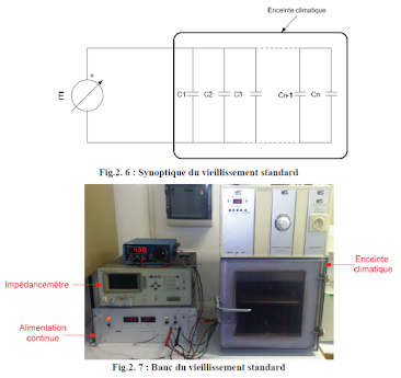
Étude et élaboration d’un système de surveillance et de maintenance prédictive pour les condensateurs et les batteries utilisés dans les Alimentations Sans Interruptions (ASI) by Mohamed Karim Abdennadher - Study and elaboration of a monitoring and predictive maintenance system for capacitors and batteries used in Uninterruptible Power Supplies (UPS)


Étude et élaboration d’un système de surveillance et de maintenance prédictive pour les condensateurs et les batteries utilisés dans les Alimentations Sans Interruptions (ASI) Mohamed Karim Abdennadher

Study and elaboration of a monitoring and predictive maintenance system for capacitors and batteries used in Uninterruptible Power Supplies (UPS)

THESE DE DOCTORAT Présentée devant L’UNIVERSITE CLAUDE BERNARD LYON 1 Pour l’obtention du grade de DOCTEUR de l’UNIVERSITE de LYON 1 (Arrêté du 07 Août 2006) Spécialité : GENIE ELECTRIQUE Préparée au sein de L’ECOLE DOCTORALE ELECTRONIQUE, ELECTROTECHNIQUE, AUTOMATIQUE DE LYON Par M. Mohamed Karim ABDENNADHER

Résumé

 To ensure power quality and permanently, some electronic system supplies exist. These supplies are the Uninterrupted Power Supplies (UPS). An UPS like any other system may have some failures. This can be a cause of redundancy loss. This load loss causes a maintenance downtime which may represent a high cost. We propose in this thesis to work on two of the most sensitive components in the UPS namely electrolytic capacitors and lead acid batteries. In a first phase, we present the existing surveillance systems for these two components, highlighting their main drawbacks. This allows us to propose the specifications which have to be implemented for this system. For electrolytic capacitors, we detail different stages of characterization ; the aging accelerated standard experimental procedure and their associated results. On the other hand, we present the simulation results of monitoring and failure prediction system retained. We discuss the experimental validation, describing the developed system. We detail the electronic boards designed, implemented algorithms and their respective constraints for a real time implementation. Finally, for lead acid batteries, we present the simulation results of the monitoring system adopted to obtain the SOC and SOH. We describe the aging experimental procedure of charging and discharging cycles of the batteries needed to find a simple and accurate electric models. We explain the aging experimental results and in the end we give suggestions for improving our system to get a more accurate SOH.

LINK:  https://tel.archives-ouvertes.fr/tel-00532642v2/document

terça-feira, 6 de outubro de 2020

SISTEMA FOTOVOLTAICO DE PEQUENO PORTE INTERLIGADO À REDE ELÉTRICA by Eldin Mario Miranda Terán Dissertação submetida à Universidade Federal do Ceará como parte dos requisitos para obtenção do grau de Mestre em Engenharia Elétrica. Orientador: Prof. Dr. René Pastor Torrico Bascopé


INTRODUÇÃO GERAL 
Em meados do século XVIII a Grã Bretanha presenciou o inicio da Revolução Industrial: um conjunto de avanços tecnológicos que mudaram todo o sistema produtivo conhecido até então. O motor a vapor e depois o motor a combustão foram os principais atores nesta revolução. Esta revolução espalhou-se rapidamente pela Europa, pelos Estados Unidos e pelo mundo todo no século XIX. Paralelamente, grandes avanços na área da eletricidade foram realizados e a máquina elétrica foi desenvolvida. Já no século XX muitos países atingiram altos níveis de industrialização enquanto a energia elétrica mudou o estilo de vida da humanidade toda. A energia primária que foi usada para impulsionar esta revolução e que ainda continua alimentando o sistema produtivo do planeta é baseada em combustíveis fósseis e carvão. No ano de 2009 aproximadamente 88% do consumo energético mundial teve origem nestas fontes (petróleo, carvão e gás natural) [1]. É sabido que esta dependência global dos combustíveis fósseis tem provocado sérios problemas no clima do planeta e que no futuro o custo da sua produção vai aumentar mais e mais, a medida que seja mais complexo realizar a exploração destes recursos, ocasionando problemas econômicos e sociais. Diante deste panorama, as fontes de energia renovável, como a solar, hidráulica e eólica entre outras, perfilam-se a ser a solução à demanda energética no futuro, sendo uma resposta tecnicamente viável e amigável com o meio ambiente, porém cara, quando comparada com as tecnologias convencionais na atualidade, precisando de subsídios e apoio dos governos para serem implementadas1 [2]. Em países altamente desenvolvidos como Espanha, Alemanha, Itália, Japão e outros, há diversos incentivos tributários a produção de energia renovável, entretanto, na América do Sul ainda não se conta com legislações que incentivem a produção de energia renovável em grande escala. A eletrônica de potência desempenha um papel importante na atividade de processamento da energia renovável, particularmente das energias fotovoltaica e eólica. No caso da energia fotovoltaica tem-se uma fonte de corrente contínua que deve ser transformada em corrente alternada para ser interligada aos sistemas elétricos e às cargas elétricas convencionais. Este processamento de energia é realizado mediante o uso da eletrônica de potência, através de conversores estáticos. Assim, neste trabalho foi desenvolvido um sistema de energia fotovoltaica de pequeno porte interligado à rede elétrica, formado por dois estágios de processamento de energia:  O primeiro estágio é um conversor cc-cc elevador (Boost) responsável por aumentar a tensão entregue pelos painéis fotovoltaicos a uma tensão adequada para ser transformada em corrente alternada e, por extrair a máxima potência elétrica disponível nos painéis fotovoltaicos.  O segundo estágio é um conversor cc-ca Full-Bridge (ponte completa) responsável por transformar a corrente continua entregue pelo primeiro estágio em corrente alternada num nível de tensão, frequência e fase úteis à rede elétrica de baixa tensão. No capítulo 1 do trabalho tem-se uma revisão bibliográfica geral focada na área da eletrônica de potência, ou seja, nas topologias de conversores aplicáveis em sistemas fotovoltaicos interligados à rede elétrica. Além disso, apresenta-se informação sobre energia solar fotovoltaica com foco nas técnicas de rastreamento de máxima potência, os objetivos do trabalho e a proposta do estudo. Nos capítulos 2 e 3 são apresentados o primeiro estágio (cc-cc) e segundo estágio (cc-ca) de processamento de energia, respectivamente. As topologias escolhidas são analisadas qualitativa e quantitativamente e os projetos dos conversores são realizados; também é detalhada a técnica de rastreamento de máxima potência (MPPT) usada no primeiro estágio e a metodologia de controle aplicada no segundo estágio. Finalmente, no capitulo 4 são apresentados resultados de simulação complementados com resultados experimentais para validar os estudos teóricos feitos nos capítulos anteriores. 

domingo, 4 de outubro de 2020

Design of Delta Primary - Transposed zigzag Secondary (DTz) Transformer to Minimize Harmonic Currents on the Three-phase Electric Power Distribution System Chairul Gagarin Irianto, Rudy Setiabudy, and Chairul Hudaya Department of Electrical Engineering, Universitas Trisakti, Jakarta, Indonesia


Design of Delta Primary - Transposed zigzag Secondary (DTz) Transformer to Minimize Harmonic Currents on the Three-phase Electric Power Distribution System Chairul Gagarin Irianto, Rudy Setiabudy, and Chairul Hudaya

Department of Electrical Engineering, Universitas Trisakti, Jakarta, Indonesia

Abstract: The delta primary - transposed zigzag secondary (DTz) transformer has been designed and used to reduce the bad impacts of the harmonic in the distribution power system. The DTz transformer is constructed with delta connection in primary winding and the three transposed windings at the different core legs of secondary winding. The harmonic reduction method of the DTz transformer applies two basic principles. The first principle is to inhibit electromagnetic energy of the harmonic currents by cancelling the phase polarity on the secondary winding. The second is to insulate the remaining of the mmf induction from harmonic current loads and minimize to circulate in the delta windings on the primary side. The triplen harmonics currents generated on the primary and secondary winding of DTz transformer are simulated in this paper. Both balanced and unbalanced loads of the three-phase distribution system are examined. The experiment shows that the total THD current in the secondary winding when balanced loads are applied is about 70.8 %, and in the primary side is 24.3 %. While for unbalanced loads, the average THD in secondary winding is 68.44 % and in delta winding is 26.4 %. It means the DTz transformer has a filter-ability to reduce about 42 - 46 % THD for both balanced and unbalanced loads. By comparing the computer simulation results and data measurements through experiment in the laboratory, it is proved that the use of the proposed DTz transformer is one of the methods to reduce harmonic currents and inhibit them to enter to the supply system.

Keywords: triplen harmonic currents, balanced and unbalanced loads, delta primary - transposed zigzag secondary winding (DTz) transformer, non-linear loads

LINK:https://www.researchgate.net/profile/Chairul_Hudaya/publication/267838702_Design_of_Delta_Primary_-Transposed_zigzag_Secondary_DTz_Transformer_to_Minimize_Harmonic_Currents_on_the_Three-phase_Electric_Power_Distribution_System/links/546d39d30cf26e95bc3caf85/Design-of-Delta-Primary-Transposed-zigzag-Secondary-DTz-Transformer-to-Minimize-Harmonic-Currents-on-the-Three-phase-Electric-Power-Distribution-System.pdf