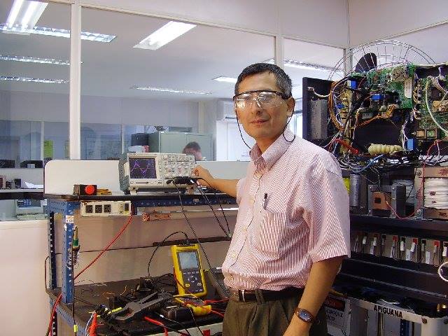
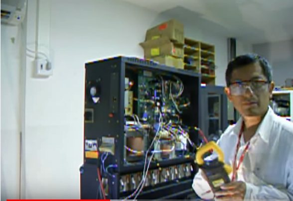
AUTOR DO BLOG ENG.ARMANDO CAVERO MIRANDA SÃO PAULO BRASIL

"OBRIGADO DEUS PELA VIDA,PELA MINHA FAMILIA,PELO TRABALHO,PELO PÃO DE CADA DIA,PROTEGENOS DO MAL"

"OBRIGADO DEUS PELA VIDA,PELA MINHA FAMILIA,PELO TRABALHO,PELO PÃO DE CADA DIA,PROTEGENOS  DO MAL"

“SE SEUS PROJETOS FOREM PARA UM ANO,SEMEIE O GRÂO.SE FOREM PARA DEZ ANOS,PLANTE UMA ÁRVORE.SE FOREM PARA CEM ANOS,EDUQUE O POVO.”

“Sixty years ago I knew everything; now I know nothing; education is a progressive discovery of our own ignorance. Will Durant”

segunda-feira, 27 de novembro de 2023

Stability problems of PV inverter in weak grid: a review-Qianjin Zhang, Mingxuan Mao, Guo Ke, Lin Zhou, Bao Xie-State Key Laboratory of Power Transmission Equipment & System Security and New Technology, Chongqing University, Chongqing 400044,People's Republic of China-IET POWER ELECTRONICS


Stability problems of PV inverter in weak grid:a review Qianjin Zhang1, Mingxuan Mao1,2, Guo Ke1, Lin Zhou1, Bao Xie11State Key 
Laboratory of Power Transmission Equipment & System Security and New Technology, Chongqing University, Chongqing 400044,People's Republic of China
2Postdoctoral Station of Electrical Engineering, Chongqing University, Chongqing 400044, People's Republic of China E-mail: mingxuan_mao@cqu.edu.cn

Abstract:

 Photovoltaic (PV) power generation, as one important part of renewable energy, has been greatly developed in recentyears. The stability of PV inverters is very important for the normal operation of PV systems. However, most PV systems,especially the large PV plants, locate in rural areas. The corresponding equivalent grid impedance is rather large and easy tolead to stability problems of grid-connected inverters and many researches have been done focusing on the stability problems.In this study, a survey of stability problems of PV inverters on weak grid condition is given. The stability problems are mainlydivided into two parts, i.e. the control loops instability and inverter output voltage instability. The control loops cover the currentloop and dc voltage loop. The output voltage instability refers to the voltage phasors relationship and the application of reactivepower compensation. The non-linear parts of inverter dead-time, digital control delay, and phase-locked loop are explored.Future trends and challenges are given

VIEW FULL TEXT

domingo, 26 de novembro de 2023

Modelling and analysis of medium frequency transformers for power converters -Piotr Dworakowski-DOCTORAL DISSERTATION-Electric power.Gdansk University of Technology,2020.


Modelling and analysis of medium frequency transformers for power converters -Piotr Dworakowski-DOCTORAL DISSERTATION-Electric power.Gdansk University of Technology,2020. 

 ABSTRACT 
The evolutions in power systems and electric vehicles, related to the economic opportunities and the environmental issues, bring the need for high power galvanically isolated DC-DC converter. The medium frequency transformer (MFT) is one of its key components, enabled by the increasing switching frequency of modern power semiconductors like silicon carbide transistors or diodes. The increased operating frequency offers small converter size, leading to the decrease in raw material usage. Most likely this will result in the converter cost reduction which will further increase the demand for solid state transformer solutions. The modeling and analysis are essential in the development of the MFT technology which is attracting lots of research and industrial interest. In this dissertation the isolated DC-DC converter topologies are introduced with the particular focus on the dual active bridge (DAB). The key components of the isolated DC-DC converters, power semiconductors and medium frequency transformer are reviewed. A mathematical model of a 3-phase MFT in the isolated DC-DC power converter, suitable in electromagnetic transient and steady state simulation is developed. The transformer modeling methods are reviewed and the Lagrange energy method is used to derive a physically motivated model for circuit analysis. The model involves a matrix of nonlinear magnetizing inductances and a matrix of linear leakage inductances, both including self and mutual values. The macroscopic models of magnetic hysteresis are reviewed and the feedback Preisach model is developed. The design of a 3-phase 20 kHz transformer for a 100 kW 1.2 kV isolated DC-DC power converter is presented. The particular focus is put on the winding and core design, and power loss and thermal calculations which are the most critical aspects of the high-power density transformer. The design results in two 3-phase MFT prototypes, first of its kind worldwide. A finite element model of the transformer is developed allowing to determine the magnetic flux characteristic Φ(Θ) and the related inductances required in the circuit model. The finite element model is based on the measured equivalent B(H) and homogenized material properties. Other model parameters are calculated analytically and compared against the measurement on the prototype MFT. The dissertation is concluded showing the technical feasibility and benefits of the 3-phase MFT. The developed MFT prototype operating at 20 kHz is more than 10 times lighter than the equivalent 50 Hz transformer. The 3-phase 100 kW DC-DC converter efficiency is measured 99.2% which is an impressive result. The efficiency of the 3-phase DC-DC is higher than its equivalent single-phase variant. A challenge of high power MFT design related to the parasitic air gaps in the core is highlighted. The influence of the air gaps on core power loss is confirmed showing that the increase in the air gap size in a certain range causes a decrease in the core power loss. In the 3-phase MFT prototype the parasitic air gaps do not cause any measurable effect on winding power loss and temperature. It is shown that the relative magnetic permeability is nonlinearly decreasing with the increase of the number of parasitic air gaps. An exponential interpolation function is proposed allowing to estimate the equivalent magnetic permeability, average air gap length and magnetizing inductance for any high-power ferrite core MFT with a similar core assembly. The proposed MFT equivalent circuit model is proven accurate in steady state and transient analyses. The no-load inrush test confirms the importance of the magnetic cross saturation involved in the magnetizing inductance model. The influence of the mutual leakage inductance on the operation of the DAB converter is shown. The feedback Preisach model of hysteresis is proven accurate in the modeling of hysteresis loops in the multi air gap ferrite core MFT.
VIEW FULL TEXT:

Active Gate Drivers for High-Frequency Application of SiC MOSFETs-BY Alejandro Paredes Camacho-Thesis submitted in partial fulfilment of the requirement for the PhD degree issued by the Universitat Politècnica de Catalunya, in its Electronic Engineering Program.

Active Gate Drivers for High-Frequency Application of SiC MOSFETs-BY Alejandro Paredes Camacho-Thesis submitted in partial fulfilment of the requirement for the PhD degree issued by the Universitat Politècnica de Catalunya, in its Electronic Engineering Program. 

 Abstract 
The trend in the development of power converters is focused on efficient systems with high power density, reliability and low cost. The challenges to cover the new power converters requirements are mainly concentered on the use of new switching-device technologies such as silicon carbide MOSFETs (SiC). SiC MOSFETs have better characteristics than their silicon counterparts; they have low conduction resistance, can work at higher switching speeds and can operate at higher temperature and voltage levels. Despite the advantages of SiC transistors, operating at high switching frequencies, with these devices, reveal new challenges. The fast switching speeds of SiC MOSFETs can cause over-voltages and over-currents that lead to electromagnetic interference (EMI) problems. For this reason, gate drivers (GD) development is a fundamental stage in SiC MOSFETs circuitry design. The reduction of the problems at high switching frequencies, thus increasing their performance, will allow to take advantage of these devices and achieve more efficient and high power density systems. This Thesis consists of a study, design and development of active gate drivers (AGDs) aimed to improve the switching performance of SiC MOSFETs applied to high-frequency power converters. Every developed stage regarding the GDs is validated through tests and experimental studies. In addition, the developed GDs are applied to converters for wireless charging systems of electric vehicle batteries. The results show the effectiveness of the proposed GDs and their viability in power converters based on SiC MOSFET devices.

VIEW FULL TEXT:

quarta-feira, 22 de novembro de 2023

13.56 MHz high power and high efficiency inverter for dynamic EV charging systems A DISSERTATION SUBMITTED TO THE GRADUATE SCHOOL OF ENGINEERING AND SCIENCE OF SHIBAURA INSTITUTE OF TECHNOLOGY by NGUYEN KIEN TRUNG IN PARTIAL FULFILLMENT OF THE REQUIREMENTS FOR THE DEGREE OF DOCTOR OF PHILOSOPHY SEPTEMBER 2016


13.56 MHz high power and high efficiency inverter for dynamic EV charging systems
A DISSERTATION SUBMITTED TO THE GRADUATE SCHOOL OF ENGINEERING AND SCIENCE OF SHIBAURA INSTITUTE OF TECHNOLOGY by NGUYEN KIEN TRUNG IN PARTIAL FULFILLMENT OF THE REQUIREMENTS FOR THE DEGREE OF DOCTOR OF PHILOSOPHY SEPTEMBER 2016

 Abstract 
Recently, Electric Vehicles (EVs) are a promising solution for reduc- ing CO2 emission and air pollution in the big cities. However, until now, the EVs have been not so attractive to consumers due to the short running distance, long charging time and high battery cost. The dynamic charging solution has been proposed to reduce the energy de- pendence and battery cost of EVs. As the demand of that systems, a 13.56 MHz high power inverter with the eciency of over 95% is re- quired. With the previous researches, there are three major research challenges have been recorded. At very high switching frequency such as 13.56 MHz, the in uence of the parasitic elements in the circuit is the rst challenge because it strongly a ect both of power and drive circuit of the inverter. Consequently, the inverter may be damaged or unstable. Secondly, the switching and gate drive power loss in the inverter are also the challenge when it proportionally increase with the switching frequency. At 13.56 MHz, it is dicult to obtain the extremely high eciency such as 95%. Finally, the high output power required is another challenge due to the low rate-parameters and the challenges in the parallel connecting of the high speed switching de- vices. To overcome these challenges, a number of the analyses and proposed design are presented in this dissertation. Firstly, the e ect of the parasitic elements in the high switch- ing frequency half-bridge inverter is analyzed and evaluated in detail based on the perspective of the ringing loop in the circuit. Based on these, an optimized PCB design is proposed to minimize the parasitic inductance in the ringing loop of the inverter. With the improved PCB, the experiment results show that, the peak voltage and the am- plitude of the ringing current in the circuit is reduced. However, the ZVS condition and the stability of the inverter at high input voltage condition are not achieved due to the high frequency ringing in the circuit. Therefore, a ringing damping circuit is proposed. The high stability and the low power loss on the proposed damping circuit is the advantage to obtain high eciency of the inverter. In the ex- periment results, the ringing current in the circuit is damped. A 1.2 kW output power is obtained with the eciency of 93.1%. This is an improvement in the 13.56 MHz inverter. However, it does not meet the required eciency of the inverter for the dynamic EV charging systems due to limited switching speed of the silicon-MOSFET. Secondly, to improve the eciency of the inverter, the GaN HEMT device is used. In an experiment, the inverter using GaN HEMT obtains the eciency of 97.5% which shows the potential to meet the required eciency of the inverter for the dynamic EV charging systems. However, the output power of the inverter is limited due to the low rate current of the GaN HEMT. And the parallel connection of GaN HEMT devices at 13.56 MHz is very dicult because of the strong unbalance dynamic current distribution. Therefore, a design using multiphase resonant inverter is proposed. The proposed module design, the proposed power loss analysis method to obtain highest eciency and the proposed drive circuit design have been addressed in detail. In experiment, a 3 kW inverter with the eciency of 96.1% is achieved that signi cantly improves the eciency of 13.56 MHz inverter. A 10 kW inverter with the eciency of over 95% will be developed by following this proposed design in near future. Finally, the 13.56 MHz high power inverter with the eciency of over 95% can be realizable. However, the Class DE operation mode which is used in multiphase resonant inverter requires exact parameter of load, resonant circuit and several turning in the experiment process. Therefore, it is still dicult to apply in the dynamic charging systems where the parameters of the coupling system will always change in the operation. The inverter behavior analysis and the further researches to keep the soft switching condition in the operation with the dynamic coupling system are necessary in the future work.
VIEW FULL TEXT:

ISLANDING DETECTION AND POWER QUALITY ANALYSIS IN MICROGRID a Dissertation Submitted to the GRADUATE SCHOOL OF ENGINEERING AND SCIENCE OF SHIBAURA INSTITUTE OF TECHNOLOGY by TRAN THANH SON


 ISLANDING DETECTION AND POWER QUALITY ANALYSIS IN MICROGRID 

a Dissertation Submitted to the GRADUATE SCHOOL OF ENGINEERING AND SCIENCE OF SHIBAURA INSTITUTE OF TECHNOLOGY 
by TRAN THANH SON 
IN PARTIAL FULFILLMENT OF THE REQUIREMENTS FOR THE DEGREE OF DOCTOR OF PHILOSOPHY SEPTEMBER 2019

Abstract
The microgrid (MG) has been developed based on the important con- cept of distributed generation (DG) with high penetration of renew- able energy integrated with energy storage systems (ESSs). MGs can operate in both grid-connected and islanding mode. Therefore, this thesis focuses on autonomous multi-islanded entities and the seamless reconnection to the main grid as the self-healing ability of the fu- ture power system. The minimization of power quality issues (mainly that of voltage, frequency, and harmonics) in such entities based on controllers, with or without intercommunication, is also an important part of this thesis. The future power system, with the signi cant pen- etration of distributed generations (DGs), can rapidly respond to any problem occurring within it by separating into autonomous islanded entities to prevent the disconnection of DGs. As a result, high-quality and continuous power is supplied to consumers. The future research that is necessary for the realization of the future power system is discussed.

Besides, the emergence of Distributed Generation (DG) in the elec- tric system has brought about the appearance of the islanding phe- nomenon. In AC networks, there are a lot of Islanding Detection Methods (IDMs) have been studied. However, not too much IDMs in DC networks have been published because of the absence of frequency and reactive power. The active IDM based on injected perturbation signal and rate of change of power output is proposed. This IDM can detect islanding condition not only in the worst case (the power of the load and PV are equal) but also in another case (the power of load is greater than the power of PV). It can be applied to both single

and multi-PV operation scenarios. Also, the cancellation problem is analyzed and the solution is proposed to solve this problem. Besides, the e ectiveness of the proposed method, the cancellation problem, and the solution are verified by simulation in Matlab/Simulink.

VIEW FULL TEXT: https://shibaura.repo.nii.ac.jp/records/141