quarta-feira, 15 de julho de 2015
segunda-feira, 6 de julho de 2015
A Comprehensive Study of Dual Active Bridge Converter and Deep Belief Network Controller for Bi-directional Solid State Transformer - Kim, Sul-Gi School of Electrical and Computer Engineering (Electrical Engineering)


A Comprehensive Study of Dual Active Bridge Converter and Deep Belief Network Controller for Bi-directional Solid State Transformer - Kim, Sul-Gi School of Electrical and Computer Engineering (Electrical Engineering)
Ulsan National Institute of Science and Technology-KOREA
ABSTRACT
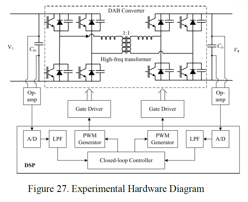
This dissertation presents a comprehensive study of Dual Active Bridge (DAB) converter and
Deep Belief Network (DBN) controller for bi-directional Solid State Transformers (SSTs).
The first contribution is to propose a dc-dc DAB converter as a single stage SST. The proposed
converter topology consists of two active H-bridges and one high-frequency transformer. Output
voltage can be regulated when input voltage changes by phase shift modulation. Power is transferred
from the first bridge to the second bridge. It analyzes the steady-state operation.
The second contribution is to develop an average model for dc-dc DAB converters. The
transformer current in DAB converter is purely ac, making continuous-time modeling is difficult.
Instead, the proposed approach uses the only 1st order terms of transformer current and capacitor
voltage as state variables.
The third contribution is the controller design of a dc-dc DAB converter. The PI gains are allowed
to vary within a predetermined range and therefore eliminate the problems from the conventional PI
controller. The performance of the proposed artificial intelligence gain scheduled PI controller is
simulated and compared with the conventional fixed PI controller under steady state error,
responding time and load disturbances.
The experimental system of DAB converter is implemented using digital signal processing unit,
Texas Instrument TMS320F28335 control board, to examine and verify the performance of the
proposed controller under various operating conditions. Simulation and experimental results show a
good improvement in transient as well as steady state response of the proposed controller. However,
power efficiency, computation burden and complexity of algorithm are disadvantage of proposed
algorithm.
Power Your Life Seminar Brazil ST
FOI REALIZADO COM MUITO EXITO PELA EMPRESA ST Power Your Life Seminar Brazil NOS DIA 3 MARÇO DE 2015 O PROGRAMA DO CURSO FOI

DEVO AGRADECER O CONVITE AO ENGENHEIRO ROGERIO BUENO DA ST E PARABENIZARLO POR SUA BRILHANTE EXPOSIÇAO JUNTO COM TODOS OS DEMAIS PALESTRANTES.
COMO PARTE DO MATERIAL DO SEMINARIO APRESENTOU UM DOS TEMAS
MAIS NOVEDOSOS
Primary side sensing techniques: design issues and implementation
Autor: Jianwen Shao


 LINK AO ARTIGO COMPLETO EM PDF :
https://copy.com/8YskwkuocttxJcko

DEVO AGRADECER O CONVITE AO ENGENHEIRO ROGERIO BUENO DA ST E PARABENIZARLO POR SUA BRILHANTE EXPOSIÇAO JUNTO COM TODOS OS DEMAIS PALESTRANTES.
COMO PARTE DO MATERIAL DO SEMINARIO APRESENTOU UM DOS TEMAS
MAIS NOVEDOSOS
Primary side sensing techniques: design issues and implementation
Autor: Jianwen Shao


https://copy.com/8YskwkuocttxJcko
quarta-feira, 1 de julho de 2015


SIMULATIONS OF FLYBACK CONVERTER WITH PSPICE
APRESENTOU A VOCES A SIMULAÇÃO DE UN TIPICO FLYBACK CONVERTER CON O SIMULADOR PSPICE ,MUITO CONHECIDO PELOS ESTUDANTES E ENGENHEIROS ELETRICOS E ELETRÕNICOS ,ESTE CIRCUITO E USADO EM TODAS AS FONTES DE UPS
TAMBEM COMO FONTE DE ALIMENTAÇÃO DE ALTA FREQUENCIA DE MUITOS CIRCUITOS ELETRÕNICOS,NATURALMENTE PREVIAMENTE TEM QUE DISENHARSE OS VALORES DOS COMPONENTES USANDO FORMULAS O MEDIANTE O PROGRAMA MATHCAD.
MUITAS PESSOAS NÃO GOSTAM DO PSPICE PORQUE MUITAS VECES DA FALHA DE CONVERGENCIA,MAIS EXISTEM DICAS E MACETES QUE NOS PEMITEM SIMULAR QUALQUER CIRCUITO SEM PROBLEMA.

SE VOCE E UM BOM OBSERVADOR VERIFICARA QUE O PINO4 DO CIRCUITO INTEGRADO DE CONTROLE PWM DE CORRENTE SG1844 NÃO ESTA CONECTADO ,POR ISSO ELE TEM UM CIRCULO VERDE QUE APARECE APOS A SIMULAÇÃO DO CIRCUITO.
ENTÃO COMO VAMOS DEFINIR A FREQUENCIA DO CIRCUITO SE NOS NÃO PODEMOS CONECTAR O CIRCUITO RC AO PINO4 DO INTEGRADO,MUITO SIMPLE SE FAZEMOS UM CLIK COM O MOUSE ACIMA DO CIRCUITO SG1844 ,APARECERA UMA NOVA FIGURA COMO A SEGUINTE COM AS PROPIEDADES DO CIRCUITO INTEGRADO AQUI VAMOS CONFIGURAR O TEMPO MORTO (DEAD TIME) E A FREQUENCIA DE CONMUTAÇÃO DO MOSFET ( PERIODO=T seg)
NESTE CASO COLOCAREMOS:
DEAD TIME = 2e-6
PERIODO = 25 us ( internamente 25us mais na saida do circuito vamos ter T=50us ou f=20khz para disparar o MOSFET ,voces podem verificar pessoalmente esta dica. )
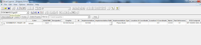


E MUITO IMPORTANTISSIMO A CONFIGURAÇÃO DO PARAMETRO K LINEAR QUE FAZ O ACOPLO MAGNETICO ENTRE OS INDUTORES L1,L2,L3,L4.L5.L6 ,NORMALMENTE SE USA COMO COEFICIENTE DE ACOPLAMENTO COUPLING=0.998.
O SUCESSO DA SIMULAÇÃO DO CIRCUITO VAI DEPENDER DO CORRETO DISENHO
ELETRICO DO CIRCUITO,LEMBRANDONOS QUE EN TUDO CIRCUITO FLYBACK AS BOBINAS DO PRIMARIO E AS BOBINAS DO SECUNDARIO ESTÃO EM CONTRAFASE DESFASADAS 180° GRADOS.
OBSERVE QUE AS BOBINAS TEM NOS TERMINAIS OS PONTOS 1 (INICIO DA BOBINA)E PONTO 2 (FIM DE BOBINA)


TAMBEM COMO FONTE DE ALIMENTAÇÃO DE ALTA FREQUENCIA DE MUITOS CIRCUITOS ELETRÕNICOS,NATURALMENTE PREVIAMENTE TEM QUE DISENHARSE OS VALORES DOS COMPONENTES USANDO FORMULAS O MEDIANTE O PROGRAMA MATHCAD.
MUITAS PESSOAS NÃO GOSTAM DO PSPICE PORQUE MUITAS VECES DA FALHA DE CONVERGENCIA,MAIS EXISTEM DICAS E MACETES QUE NOS PEMITEM SIMULAR QUALQUER CIRCUITO SEM PROBLEMA.

SE VOCE E UM BOM OBSERVADOR VERIFICARA QUE O PINO4 DO CIRCUITO INTEGRADO DE CONTROLE PWM DE CORRENTE SG1844 NÃO ESTA CONECTADO ,POR ISSO ELE TEM UM CIRCULO VERDE QUE APARECE APOS A SIMULAÇÃO DO CIRCUITO.
ENTÃO COMO VAMOS DEFINIR A FREQUENCIA DO CIRCUITO SE NOS NÃO PODEMOS CONECTAR O CIRCUITO RC AO PINO4 DO INTEGRADO,MUITO SIMPLE SE FAZEMOS UM CLIK COM O MOUSE ACIMA DO CIRCUITO SG1844 ,APARECERA UMA NOVA FIGURA COMO A SEGUINTE COM AS PROPIEDADES DO CIRCUITO INTEGRADO AQUI VAMOS CONFIGURAR O TEMPO MORTO (DEAD TIME) E A FREQUENCIA DE CONMUTAÇÃO DO MOSFET ( PERIODO=T seg)
NESTE CASO COLOCAREMOS:
DEAD TIME = 2e-6
PERIODO = 25 us ( internamente 25us mais na saida do circuito vamos ter T=50us ou f=20khz para disparar o MOSFET ,voces podem verificar pessoalmente esta dica. )


E MUITO IMPORTANTISSIMO A CONFIGURAÇÃO DO PARAMETRO K LINEAR QUE FAZ O ACOPLO MAGNETICO ENTRE OS INDUTORES L1,L2,L3,L4.L5.L6 ,NORMALMENTE SE USA COMO COEFICIENTE DE ACOPLAMENTO COUPLING=0.998.
O SUCESSO DA SIMULAÇÃO DO CIRCUITO VAI DEPENDER DO CORRETO DISENHO
ELETRICO DO CIRCUITO,LEMBRANDONOS QUE EN TUDO CIRCUITO FLYBACK AS BOBINAS DO PRIMARIO E AS BOBINAS DO SECUNDARIO ESTÃO EM CONTRAFASE DESFASADAS 180° GRADOS.
OBSERVE QUE AS BOBINAS TEM NOS TERMINAIS OS PONTOS 1 (INICIO DA BOBINA)E PONTO 2 (FIM DE BOBINA)


Assinar:
Postagens (Atom)


 JOSIL ARTISTA PLASTICO FORTALEZA CEARA BRASIL AV.HERACLITO GRAÇA 41 TEL(85)32542378