segunda-feira, 25 de junho de 2018
A Study on the Development of BLDC High Efficiency Motor for Electric Vehicle Drive By Jung, Bo-Won Department of Mechanical Engineering Graduate School of Chosun University
A Study on the Development of BLDC High Efficiency Motor for Electric Vehicle Drive By Jung, Bo-Won
Department of Mechanical Engineering Graduate School of Chosun University
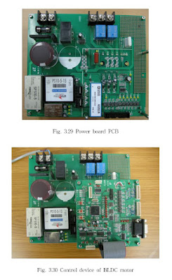
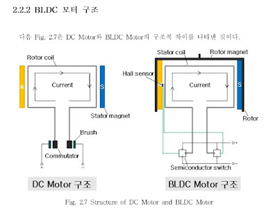
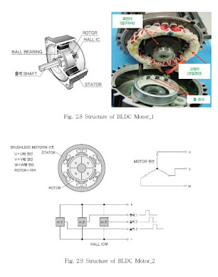
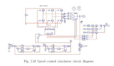
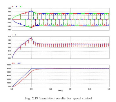
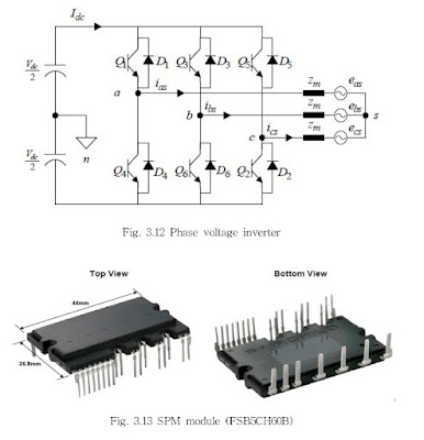
In the past, the automobile industry market showed off the large displacement and high-power & high-performance technical power focusing on internal combustion engine. Due to the instability of oil price, however, it started developing/mass-producing vehicles with low displacement & high fuel-efficiency. Thus, the domestic automobile industry is continuously growing into the national core industry by developing vehicles with low displacement & high fuel-efficiency. However, because of car exhaust after using fossil fuels for a long time, the environmental problem is largely highlighted, and the issue of climate change was discussed with the development of automobile industry. Therefore, the environment-friendly trend could be found in the recent world automobile industry. On top of electric car, the R&D of environment-friendly vehicles such as fuel cell vehicle and hybrid vehicle is actively performed. In case of environment-friendly vehicles, they are driving only with electric motor without engine, or the engine and electric motor are composed as serial, parallel, or serial-parallel. When driving, the high-efficiency driving is possible by combining engine and electric motor. When braking, as equipped with the regenerative braking ability to collect energy, the fuel-efficiency could be improved more than 50% compared to the existing vehicles. The representative cases of environment-friendly vehicle include hybrid vehicle, fuel cell - X - vehicle, and electric vehicle driven by electric motor. Among them, the electric motor application technology which is the most core technology is represented as the technology of environment-friendly vehicle, so that the technical demand for it is increasing. In the world motor technology area, products for microminiaturization, high-speed, high-efficiency, high-power, and light-weight are rapidly growing. Especially, with the increased interest in environment, environment-friendly products are forming new markets. There have been active reinforcement of regulations and technical development to meet such demands for this R&D and also to reduce power consumption. Especially, due to the intensified environmental problem, drivers' interest in electric vehicle is increasing. The great amount of subsidies from government/local governments is also a factor that promotes the purchase of electric vehicles. Moreover, once the autonomous function is added to no noise, no exhaust, light-weighted engine design, and high-tech driver's seat, it is the model of the 4th industrial revolution. Currently, for the development of BLDC motor using the semiconductor switching element after removing the commutator and brush, on top of motor manufacturing businesses in the core parts industry of future automobile, even home-electronic motor manufacturers and industrial motor manufacturers are jumping in the business based on their great interest in researches on product development and quality improvement. Compared to the brush-type DC motor, the BLDC motor has better durability, and high-efficiency and high-power. As there is no brush, the electric noise and mechanical noise are less, so that there is no need of maintenance/repair work. On top of high-speed, its reliability is also high. Compared to other DC motors and AC motors, the BLDC motor has more strengths as a driving motor of electric vehicle. In spite of its high price, it has a long life and great efficiency, so that it has been a lot researched as a driving motor of electric vehicle. This paper aimed to develop the BLDC motor & driver as a driving system of 60kW-level electric vehicle. Completing the development of motor & controller for the PWM control in accordance with high-performance speed control of BLDC motor drive, the Maxwell Program was used for the detailed interpretation of the designed motor. Using the dynamo measuring system, the performance relation of motor efficiency was verified. The results of a series of motor performance test are like below. 1. In order to measure the test results of maximum output, the inverter input was measured as input voltage(VDC) 310V. The motor output was torque(Nm) 102.933Nm, the rated revolutions were 5,560rpm, and the rated output was(KW) 60.02KW. 2. In the results of the motor performance assessment by changing the angle of hall sensor by 5°, 10°, and 15° after producing a BLDC motor, when the speed value was high, and the values of torque, voltage, and watt were low, the performance efficiency was the highest. 3. In the results of dynamo test, when changing the angle of hall sensor by 5°, the maximum torque was 102.933Nm. When the maximum revolution speed was 5,560rpm with voltage(308.1V) and watt(60.02KW), the motor showed the maximum efficiency, which verified the excellence of the motor. As PWM has high efficiency, high power-factor, and high performance, it gets the limelight in the application area of drive. As the motor could be driving in a certain torque area, certain output area, and extensive driving speed range, more things could be expected from future researches. Owing to the excellent control algorithm in the aspect of responsiveness, linearity of control, switching frequency, and high-frequency percentage of output current, it is applied to many drive systems. In the future, regarding the BLDC motor & drive system for high-performance & high efficiency electric vehicles, it is expected to apply the technology to auto part-related companies, and also to contribute to the commercialization of environment-friendly electric vehicles.
quinta-feira, 21 de junho de 2018
APEC 2018 Applied Power Electronics Conference Vienna Rectifier and Beyond Johann W Kolar,
APEC 2018 Applied Power Electronics Conference Vienna Rectifier and Beyond Johann W Kolar,
AP Vienna Rectifier and Beyond - Johann W. Kolar, APEC 2018- Dr. Johann W. Kolar, Professor at ETH Zurich Institute PES, shares his keynote presentation on the Vienna Rectifier, including a brief history, comparative evaluations and further improvements on the technology
LINK : https://ieeetv.ieee.org/conference-highlights/vienna-rectifier-and-beyond-johann-w-kolar-apec-2018?rf=events|146&
quarta-feira, 20 de junho de 2018
terça-feira, 19 de junho de 2018
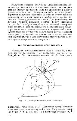
Говорков В.А.- Электрические и магнитные поля -Govorkov V.A. -Electric and magnetic fields, 1968
Govorkov V.A. Electric and magnetic fields, ed. 3rd, revised. and additional. 1968 year. 488 pages djvu. 6.6 MB. The book describes the theory of the electromagnetic field in the volume necessary for the practical calculation of the majority of stationary and alternating magnetic fields encountered in the technique of electrical communication, radio engineering, electronic engineering, power engineering, automation devices, etc. Particular attention is drawn to the graphical construction of field paintings, useful for mastering complex physical laws and being the first and necessary step in applying the theory to practice. A significant place in the book is devoted to approximate calculations of electric and magnetic fields by the method of grids. Their mastering frees the calculator from the ungrateful task of finding not always sufficiently justified approximations to the boundary conditions under which the differential equations of mathematical physics admit the so-called "exact" solutions.
LINK
http://www.mediafire.com/file/i009tizd437zfis/Govorkov%20V.A.%20CAMPOS%20ELETRICOS%20Y%20MAGNETICOS.pdf
segunda-feira, 18 de junho de 2018
Development of Photovoltaic Inverter used Grid-Connected Distributed Power Jeong-Do Kim Department of Electrical Engineering Graduate School Pukyong National University
Development of Photovoltaic Inverter used Grid-Connected Distributed Power
Jeong-Do Kim
Department of Electrical Engineering Graduate School Pukyong National University
Abstract
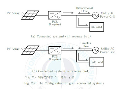
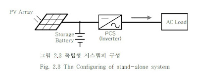
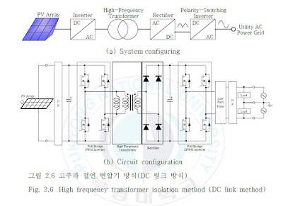
This paper relates to grid-connected single-phase inverter system, the proposed system is a gate pulse signal was added to the active auxiliary resonant circuit in the bridge arm of a conventional grid-connected single-phase half-bridge inverter, main switch is modulated by the SPWM method by configuring so that the, take a feature that can control the multi-phase alternating current can be used in the batch phase inverter. And active by the secondary resonance also work during the snubber circuit a dead time period, soft switching is possible because it actually turns a basic switch in the on state-off and resonant operation after turning the other main switch-which was applied to the whole of the gate signal have the characteristic. Further, when the conventional program is shorter than the width of the gate pulse signal active auxiliary resonant snubber operation time in the operation in the hard switching to occur even if the H, L is the reverse of the gate pulse signal. This power supply is in reversal of the power supply circuit is a short circuit may possibly be damaged since. To prevent this, this paper has set the ARCP operation time and modulation rate settings and processes the pulse of the gate pulse signal reversal was the program not to occur. Further, as the main switch is in the off state to the time when the other switch is turned on, and the dead time is a hard switching method in case of the conventional method to sequence the switching pattern 1.5[μs], While for setting the dead time of the soft switching system with 2.0[ms], For this paper the sequence switching patterns applied to the soft-switching method is 4.0[μs] because the pulse width of the hard-switched at the same modulation rate and time to get a high density to suppress the resonant inductor current as a whole small effect of improving the efficiency have. Running a soft switching operation by the switching pattern sequence scheme applied to the paper, it is possible to suppress the surge voltage and the surge current, the generation of noise of the device is reduced as compared to the effect of the hard switching method.
LINK
http://www.mediafire.com/file/fybzxwr2in0nfhq/Development%20of%20Photovoltaic%20Inverter%20used%20Grid-Connected.pdf
domingo, 17 de junho de 2018
domingo, 10 de junho de 2018
A High Efficiency LLC Resonant Converter-based Li-ion Battery Charger with Adaptive Turn Ratio Variable Scheme Yeong-Jun Choi*, Hyeong-Gu Han-Dept. of Electrical and Biomedical Engineering, Hanyang University, Korea
A High Efficiency LLC Resonant Converter-based Li-ion Battery Charger with Adaptive Turn Ratio Variable Scheme Yeong-Jun Choi*, Hyeong-Gu Han*, See-Young Choi*, Sang-Il Kim* and Rae-Young Kim†
Abstract – This paper proposes an LLC resonant converter based battery charger which utilizes an adaptive turn ratio scheme to achieve a wide output voltage range and high efficiency. The high frequency transformer of the LLC converter of the proposed strategy has an adaptively changed turn ratio through the auxiliary control circuit. As a result, an optimized converter design with high magnetizing inductance is possible, while minimizing conduction and turn-off losses and providing a regulated voltage gain to properly charge the lithium ion battery. For a step-by-step explanation, operational principle and optimal design considerations of the proposed converter are illustrated in detail. Finally, the effectiveness of the proposed strategy is verified through various experimental results and efficiency analysis based on prototype 300W Li-ion battery charger and battery pack. Keywords: LLC resonant converter, Battery charger, High efficiency, Adaptive turn ratio, Wide output voltage 1. Introduction Recently, various green transportations such as xEVs, E-bike, and E-scooter using batteries as a main power source, have expeditiously developed and penetrated the commercial marketplace. Generally, lithium-ion batteries are primarily used in such applications due to diverse reasons such as high energy densities, no memory effects and low self-discharge rates [1]. Meanwhile, the importance of the Li-ion battery charging system has also been increased to ensure safe and powerful use of the battery. Most charging systems employ a constant current-constant voltage (CC-CV) charging profile as displayed in Fig. 1 to prevent overcurrent and overcharge of the battery where the dashed line stands for a battery voltage Vbatt and the solid line stands for the battery charging current Ibatt [2]. As can be seen from the figure, the terminal voltage of the battery is widely varied from the cut-off voltage to the maximum charging voltage during the entire charging process; hence, Li-ion battery chargers should cover a wide output voltage range. LLC resonant converter is a promising high-efficiency battery charger candidate possessing several advantages [3-5]. The converter inherently achieves zero voltage switching (ZVS) of the primary side switches and soft commutation capability of semiconductor devices over the whole operational range. Therefore, the turn-on loss is small and the reverse recovery loss of the diode is reduced, so that a high switching frequency operation is possible and the power density of the entire system can be increased
Additionally the magnetic elements of the resonant tank can be integrated into a single transformer core, which isadvantageous in terms of cost.
However, the LLC resonant converter also possesses ahandicap as a battery charger: There is a trade-off in thedesign methodology to achieving high efficiency and meeting wide output voltage variations to cover wide variations in battery terminal voltage. To achieve a wide output voltage range, the LLC resonant converter need tooperate at a frequency lower than the resonant frequency.
However, such operation decreases efficiency due to the presence of a large circulating current. Moreover, a small magnetizing inductance of the resonant tank is usually required; therefore, efficiency became worse due to an excessive turn-off loss and magnetizing current. Hence, the optimal design of an LLC resonant is realized to be adelicate process [6].
To overcome this problem, several studies have been performed [7-15]. One solution is to develop a design method for resonant tanks to meet a given battery voltage and efficiency specification. [7-12]. However, these studiesonly reveal the inherent trade-off relationship limitation that cannot naturally be overcome. In the literature, a strategy of using auxiliary windings was proposed to realize a wide output voltage [13]. However, since this method was proposed for hold-up compensation, so there is no focus on maintaining the ZVS condition, and it is
difficult to apply it to a battery charger. Some other researches discussed solutions for high power applications such as 3.3kW or 6.6kW [14, 15]. The main concept of these studies is to integrate the many advantages of two or more DC-DC converters with topology modification.
However, it is impossible to apply results of theseresearches directly for low power applications below 500W.
LINK WEB
http://www.jeet.or.kr/LTKPSWeb/pub/pubfpfile.aspx?ppseq=1943
Compact DC-AC SiC Inverter for High Ambient Temperatures in Hybrid Electric Vehicles- ETH Zurich Power Electronic Systems Laboratory
Compact DC-AC SiC Inverter for High Ambient Temperatures in Hybrid Electric Vehicles
Power electronic converters are key components of Hybrid Electric Vehicles, which are in the core focus of the Research and Development activities of the automotive industry. Today’s converters feature Silicon power semiconductors with a junction temperature limit between 150 °C and 175 °C and thus their operating ambient temperature range is limited to values typically well below 80 °C. This implies undesired restrictions regarding cooling circuit requirements or the placement of the converter due to the ambient air temperature level in case of air-cooled converters.Silicon Carbide (SiC) power semiconductor switches allow to increase the junction temperature beyond 175 °C and thus to overcome the above mentioned restrictions. In this research project, an ambient-air-cooled, high power density SiC inverter system for an ambient air temperature level of 120 °C is investigated. In order to be able to fully utilize the semiconductors, the converter is designed for an optimum junction temperature of 250 °C. A high switching frequency of 50 kHz keeps volume and weight of passive components low and covers a broad range of output frequencies suitable even for driving high-speed electrical machines. It is made sure that the individual devices are operated within their specified temperature ranges by carefully choosing the component placing taking needs from an electrical point of view into account and by active Peltier cooling of the components. Some components, such as high performance fans for the air-cooling system, are currently not available on the market in the required temperature range and thus are developed as an additional part of this project. All obtained results are experimentally validated on a test high speed test bench with a 10 kW permanent magnet synchronous machine and an induction machine rotating up to 30’000 rpm.
Power Electronics Systems Laboratory DC-AC Converters
Dr. Benjamin Wrzecionko Contact ETH Zurich Power Electronic Systems Laboratory Physikstrasse 3 ETL H23 8092 Zurich Switzerland
LINK
https://www.ethz.ch/content/specialinterest/itet/power-electronic-systems-lab/en/research/research-and-thesis-projects/dc-ac-converters/DC-AC-Converters-1.html
WIRELESS CHARGING OF ELECTRIC VEHICLES Omer C. Onar, Steven Campbell, Larry Seiber, Cliff White Power Electronics and Electric Machinery Group (PEEM) Electrical and Electronics Systems Research Division (EESR)
Oak Ridge National Laboratory Wireless Charging of Electric Vehicles – CRADA Report WIRELESS CHARGING OF ELECTRIC VEHICLES
Omer C. Onar, Steven Campbell, Larry Seiber, Cliff White, Madhu Chinthavali, Lixin Tang, Paul Chambon, and Burak Ozpineci Power Electronics and Electric Machinery Group (PEEM) Electrical and Electronics Systems Research Division (EESR)
1. Abstract Wireless power transfer (WPT) is a paradigm shift in electric-vehicle (EV) charging that offers the consumer an autonomous, safe, and convenient option to conductive charging and its attendant need for cables. With WPT, charging process can be fully automated due to the vehicle and grid side radio communication systems, and is non-contacting; therefore issues with leakage currents, ground faults, and touch potentials do not exist. It also eliminates the need for touching the heavy, bulky, dirty cables and plugs. It eliminates the fear of forgetting to plug-in and running out of charge the following day and eliminates the tripping hazards in public parking lots and in highly populated areas such as shopping malls, recreational areas, parking buildings, etc. Furthermore, the high-frequency magnetic fields employed in power transfer across a large air gap are focused and shielded, so that fringe fields (i.e., magnetic leakage/stray fields) attenuate rapidly over a transition region to levels well below limits set by international standards for the public zone (which starts at the perimeter of the vehicle and includes the passenger cabin). Oak Ridge National Laboratory’s approach to WPT charging places strong emphasis on radio communications in the power regulation feedback channel augmented with software control algorithms. The over-arching goal for WPT is minimization of vehicle on-board complexity by keeping the secondary side content confined to coil tuning, rectification, filtering, and interfacing to the regenerative energy-storage system (RESS). This report summarizes the CRADA work between the Oak Ridge National Laboratory and the Toyota Research Institute of North America, Toyota Motor Engineering and Manufacturing North America (TEMA) on the wireless charging of electric vehicles which was funded by Department of Energy under DE-FOA-000667. In this project, ORNL is the lead agency and Toyota TEMA is one of the major partners. Over the course of the project, ORNL and Toyota TEMA worked closely on the vehicle integration plans, compatibility, and the interoperability of the wireless charging technology developed by ORNL for the vehicles manufactured by Toyota. These vehicles include a Toyota Prius Plug-in Hybrid electric vehicle, a Scion iQ electric vehicle, and two Toyota RAV4 electric vehicles. 2. Statement of Objectives The main objective of this project is to coordinate multi-party team for the design, development, and fabrication of WPT grid side unit (GSU), coupling coils, and the vehicle side power conditioning units. The GSU includes the active front-end rectifier with power factor correction (PFC), high-frequency power inverter, and the high-frequency isolation transformer whereas vehicle side unit includes a resonant tuning capacitor, a bridge rectifier, a filter circuit, and the additional relays and contactors that are used to timely respond to the charging request or to comply with the charging protocols that a vehicle may have (CHAdeMO, J1772, or direct battery connection). The objective of this work is to demonstrate a fully automated charging process including the alignment, start charging, stop charging, and the emergency and orderly shutdown procedures while meeting at least 6.6kW power transfer over 160mm magnetic airgap while exceeding an overall (end-to-end) efficiency of 85%. After integrating ORNL developed WPT technology into demonstration vehicles, an additional objective was to validate the system operation in an independent testing laboratory (Idaho National Laboratory) for field testing of this technology which will assist in system improvements and standards development. In this project, Evatran was the commercialization partner and under ORNL guidance worked on cost and component optimization and fabrication of GSUs and also the primary and secondary coils. Evatran also worked on vehicle integrations in coordination with ORNL and other partners. Clemson University ICAR Center was the demonstration site for phase #2 deliverables of the project. Clemson University, in collaboration with Cisco Systems, also supported the radio communications developments and radio integrations to the vehicles and the WPT equipment on the vehicles. Finally, Toyota Motor Corporation is the vehicle OEM partner provided the vehicles and collaborated with ORNL on the vehicle integrations. One last objective of this project was to demonstrate in-motion wireless charging on Toyota RAV4 vehicles to prove feasibility and collect data.
LINK FULL PAPER
https://info.ornl.gov/sites/publications/files/Pub68349.pdf
Assinar:
Postagens (Atom)















 JOSIL ARTISTA PLASTICO FORTALEZA CEARA BRASIL AV.HERACLITO GRAÇA 41 TEL(85)32542378
